NCT 공차 설계 기준
NCT 터렛펀칭과 CNC 판금 가공은 단순히 평판에 구멍을 뚫고 외곽을 절단하는 공정이 아닙니다. 이 단계에서 결정된 홀 위치, 외곽 치수, 버 방향, 절곡 기준점은 절곡과 후처리, 조립 단계까지 이어지며 최종 제품의 품질을 좌우합니다. 특히 도장, 도금, 아노다이징, 전해연마, 부동태화와 같은 후처리가 포함되는 부품은 가공 직후의 치수만으로 품질을 판단하기 어렵습니다.
판금 부품의 설계 기준은 블랭킹 직후 치수가 아니라 후처리와 절곡이 완료된 최종 기능 치수를 기준으로 설정해야 합니다. 도면상 10.00mm 홀이라도 분체 도장 후 실제 조립에 필요한 치수가 10.00mm라면, NCT 가공 단계에서는 도막 두께만큼 미리 크게 가공해야 합니다. 반대로 외곽 치수는 피막 성장량을 고려하여 작게 설계하는 방식이 필요합니다.
이러한 관점은 판금 공차 설계에서 가장 중요한 출발점입니다. 가공 공정 하나만 보면 허용 가능한 공차라도, 절곡과 후처리를 거치면 조립 불량, 간섭, 체결 불량, 외관 품질 저하로 이어질 수 있습니다. 따라서 설계자는 단품 가공성보다 전체 제조 흐름을 기준으로 공차를 배분해야 합니다.
판금 제조 공차 누적 구조
일반적인 판금 부품은 NCT 펀칭 또는 레이저 절단으로 평판 형상을 만든 뒤, 절곡으로 입체 형상을 구성하고, 마지막으로 도장이나 도금 등의 후처리를 진행합니다. 이 과정에서 각 공정의 편차는 독립적으로 사라지지 않고 다음 공정으로 전달됩니다. NCT에서 발생한 홀 위치 편차는 절곡 기준점의 오차로 작용하며, 절곡에서 발생한 각도 편차는 후처리 후 조립 간극에 영향을 줍니다.
예를 들어 1.0mm 두께의 SPCC 판재에서 NCT 홀 위치가 ±0.10mm 범위로 관리되고, 절곡 후 플랜지 치수에서 ±0.15mm에서 ±0.25mm의 편차가 발생하며, 분체 도장에서 편측 0.06mm에서 0.12mm의 피막이 형성되면 최종 조립 치수는 초기 설계값 대비 0.30mm 이상 달라질 수 있습니다. 치수 하나만 보면 작은 차이처럼 보이지만, 조립 구조에서는 체결 홀 불일치나 커버 간섭으로 나타날 수 있습니다.
공차 설계에서는 이와 같은 누적 구조를 반드시 고려해야 합니다. 모든 치수에 과도하게 엄격한 공차를 주는 방식은 제조 비용을 높이고 업체 대응력을 낮춥니다. 반대로 기능 치수와 비기능 치수를 구분하지 않으면 양산 단계에서 반복적인 수정이 발생합니다. 핵심은 조립과 기능에 직접 영향을 주는 치수에 공차 예산을 집중하고, 외관 또는 비기능 치수는 현실적인 일반 공차로 관리하는 것입니다.
NCT 터렛펀칭 전단 조건과 공차
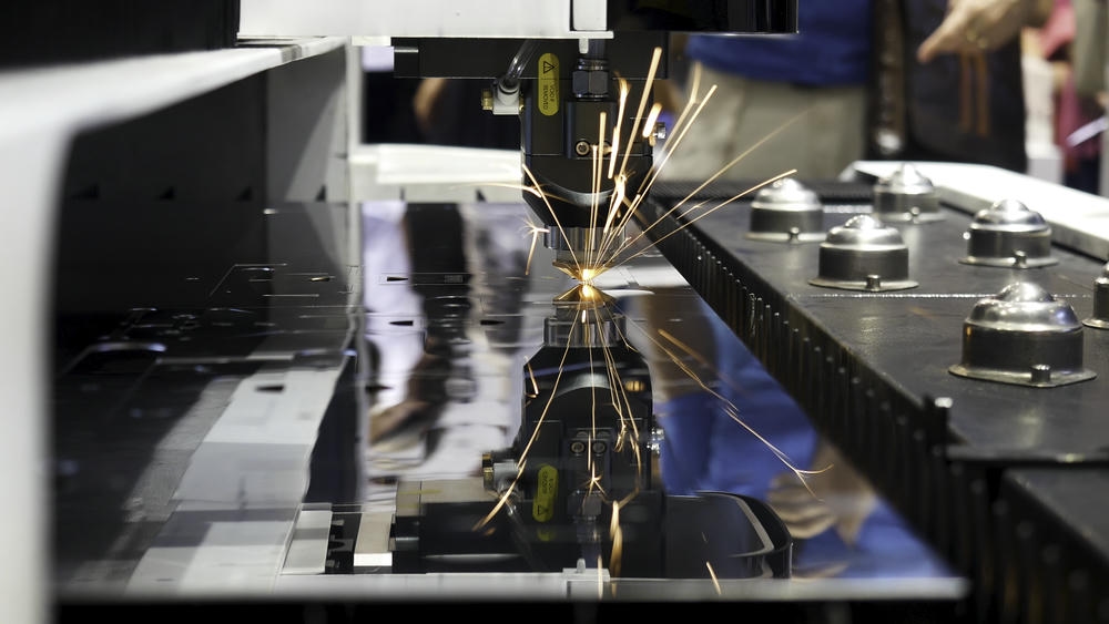
NCT 터렛펀칭은 펀치가 소재를 눌러 다이와의 간극에서 전단을 발생시키는 방식입니다. 이때 실제 치수와 절단면 품질은 펀치와 다이의 클리어런스, 판재 두께, 재질 강도, 금형 마모 상태, 클램핑 조건, 가공 순서에 따라 달라집니다. 같은 도면이라도 소재와 금형 조건이 달라지면 홀 직경, 버 높이, 절단면 조도, 치수 반복성이 달라집니다.
펀치-다이 클리어런스는 일반적으로 판재 두께의 일정 비율로 설정합니다. SPCC와 같은 냉간압연강은 두께의 약 7%에서 9% 범위가 안정적이며, SUS304와 SUS316 스테인리스는 가공 경화와 높은 항복 강도 때문에 10%에서 15% 수준으로 확대하는 경우가 많습니다. AL5052와 같은 알루미늄은 얇은 판재에서 6%에서 8% 수준으로 관리하면 절단면 품질을 확보하기 쉽습니다. 고장력강은 금형 파손을 줄이기 위해 12%에서 18%까지 클리어런스를 확대하는 방식이 사용됩니다.
클리어런스가 너무 작으면 이중 전단과 금형 마모가 증가하고, 클리어런스가 너무 크면 버와 파단면이 커지며 홀의 실효 치수가 흔들립니다. 정상적인 전단면은 롤오버, 버니시드존, 파단면, 버가 일정한 비율로 나타나야 합니다. 이 균형이 무너지면 외관 품질뿐 아니라 후처리 밀착성, 홀 체결성, 디버링 비용까지 영향을 받습니다.
금형 마모와 양산 공차 변화
NCT 금형은 사용 횟수가 누적될수록 펀치 에지가 라운딩되고, 실제 전단 조건이 초기 상태와 달라집니다. 금형 마모가 진행되면 버 높이가 증가하고 홀 직경 편차가 커지며, 절단면 파단 품질도 나빠집니다. 양산 초기에 합격하던 부품이 로트 후반부에서 불합격으로 전환되는 원인은 대부분 금형 마모, 소재 로트 변화, 클램핑 상태 변화에서 발생합니다.
정밀 홀을 NCT 단일 공정으로 완성하려는 설계는 위험합니다. 베어링 압입부, 위치 결정 핀 홀, 정렬용 기준 홀처럼 H7 수준의 정밀도를 요구하는 피처는 NCT에서 예비 홀을 만든 뒤 리머, 보링, 탭, 카운터보어 같은 후가공으로 완성하는 방식이 적합합니다. NCT는 생산성이 뛰어나지만, 고정밀 원통 공차를 안정적으로 보장하는 공정은 아닙니다.
설계 단계에서는 기능 홀을 등급별로 구분해야 합니다. 일반 체결용 관통 홀은 NCT 표준 공차로 관리하고, 정렬 기능이 있는 홀은 위치도와 후가공 여부를 별도로 지정하며, 압입 또는 회전 기준이 되는 홀은 후처리 전후 치수 보정과 검사 기준까지 명시해야 합니다. 이렇게 구분하면 도면 요구사항이 명확해지고 제조 비용도 합리적으로 관리됩니다.
후처리 피막과 치수 변화
도장, 도금, 아노다이징은 외관과 내식성을 높이는 표면처리이며, 공차 관점에서는 치수 변화까지 함께 관리해야 합니다. 특히 홀, 슬롯, 나사 체결부, 압입부, 접지면처럼 기능이 있는 부위는 피막 형성량을 반드시 계산해야 합니다. 후처리를 단순한 외관 처리로 취급하면 최종 조립 단계에서 문제가 발생합니다.
적층형 후처리는 표면 위에 새로운 층을 쌓는 방식입니다. 아연 도금, 니켈 도금, 크롬 도금, 액체 도장, 분체 도장이 여기에 해당합니다. 외경은 피막 두께만큼 커지고, 내경은 양쪽 벽면에서 피막이 성장하므로 피막 두께의 두 배만큼 작아집니다. 예를 들어 편측 0.08mm 도막이 형성되는 분체 도장 홀은 이론적으로 직경이 약 0.16mm 줄어듭니다.
아노다이징은 알루미늄 표면을 산화막으로 변환시키는 공정이며, 단순 적층형 공정과 다르게 일부는 모재 내부로 침투하고 일부는 외부로 성장합니다. 일반적으로 산화막 두께의 약 40%에서 50%가 외부로 성장하므로, 전체 두께를 그대로 외경 증가량으로 계산하면 과보정이 발생할 수 있습니다. 알루미늄 정밀 부품에서는 아노다이징 종류와 목표 막 두께를 도면에 명확히 지정하고, 실제 외측 성장량을 기준으로 홀 치수를 보정해야 합니다.
도금 치수 보정 기준
전기 도금은 평면부와 에지부의 두께가 동일하지 않습니다. 전류 밀도가 집중되는 모서리와 돌출부에서는 도금이 더 두껍게 형성될 수 있으며, 깊은 홈이나 작은 내경부에서는 상대적으로 얇게 형성될 수 있습니다. 이 현상 때문에 도금 후 홀 직경은 단순 계산값보다 더 작아지거나 위치별 편차가 커질 수 있습니다.
아연 도금은 일반적으로 편측 수 마이크로미터에서 10마이크로미터대 수준으로 관리되며, 니켈 도금은 그보다 두껍게 형성되는 경우가 많습니다. 경질 크롬 도금은 기능성 피막으로 적용될 때 더 큰 막 두께를 가질 수 있습니다. 설계자는 도금 종류, 목표 막 두께, 후처리 후 검사 치수, 마스킹 영역을 도면에 함께 지정해야 합니다.
도금이 예정된 기능 홀은 NCT 단계에서 내경을 크게 가공하거나, 도금 후 리머 작업으로 최종 치수를 맞추는 방법을 사용합니다. 단순 체결 홀은 볼트 규격보다 0.10mm에서 0.20mm 정도 여유를 더 주는 방식이 효과적이며, 정밀 끼워맞춤이 필요한 부위는 마스킹 또는 후가공을 지정하는 편이 안정적입니다. 도금 후 치수가 중요한 부품은 “가공 후 치수”와 “후처리 후 치수”를 구분하여 관리해야 합니다.
분체 도장 체결 홀과 모서리 관리
분체 도장은 내식성과 외관성이 우수하지만 막 두께가 비교적 두껍습니다. 일반적으로 건조 후 0.06mm에서 0.12mm 수준의 도막이 형성되며, 일부 사양에서는 이보다 두꺼워질 수 있습니다. 홀 내부와 코너, 절곡부, 모서리에서는 도막 분포가 균일하지 않기 때문에 설계 여유가 부족하면 체결 불량이나 조립 간섭이 발생합니다.
M4 볼트가 자유롭게 통과해야 하는 관통 홀을 예로 들면, 도장 전 4.5mm 여유 홀이라도 분체 도장 후에는 실효 직경이 약 4.3mm대까지 줄어들 수 있습니다. 볼트 공차, 도장 편차, 홀 위치 편차가 동시에 작용하면 조립 현장에서 볼트가 들어가지 않는 상황이 발생합니다. 따라서 분체 도장 부품의 체결 홀은 일반 무도장 부품보다 더 큰 여유를 적용해야 하며, 필요 시 후처리 후 홀 재가공 또는 마스킹을 지정해야 합니다.
모서리 품질도 중요합니다. 날카로운 에지는 도막이 얇아지거나 박리되기 쉽고, 코너 부위는 도막이 뭉쳐 외관 불량이 생길 수 있습니다. 분체 도장이 예정된 판금 부품은 외관면과 손 접촉부에 최소 R0.5 수준의 에지 완화를 적용하는 것이 좋습니다. 에지 완화는 안전성뿐 아니라 도장 밀착성, 부식 저항성, 외관 품질을 함께 개선합니다.
아노다이징 산화막 성장 방향
알루미늄 부품의 아노다이징은 도장이나 도금과 다른 방식으로 치수 변화가 발생합니다. 산화막은 모재 표면에서 생성되며, 일부는 내부로 침투하고 일부는 외부로 성장합니다. 일반 Type II 아노다이징은 외관과 내식성 중심으로 적용되며, Type III 하드 아노다이징은 내마모성과 기능성을 위해 두꺼운 산화막을 형성합니다.
정밀 홀, 슬라이딩 면, 베어링 접촉부, 접지면이 있는 알루미늄 부품에서는 아노다이징 두께와 성장량을 반드시 설계에 반영해야 합니다. 하드 아노다이징 50마이크로미터 사양이라면 전체 막 두께가 모두 외부로 성장하는 것이 아니므로, 실제 치수 보정은 외측 성장분을 기준으로 계산합니다. 다만 업체별 공정 조건, 합금 종류, 전해액 조건에 따라 결과가 달라질 수 있으므로 시제품 측정으로 기준값을 확정하는 것이 안전합니다.
아노다이징 후 압입이나 접지가 필요한 부위는 별도 관리가 필요합니다. 압입부에 산화막이 과도하게 형성되면 압입 하중이 달라지고, 접지면에 산화막이 남으면 전기적 접촉 저항이 증가합니다. 전자 장비, 통신 장비, 의료기기 함체에서는 접지 부위를 “Bare Metal Contact Zone”처럼 명확하게 지정하고 마스킹 또는 후가공 기준을 도면에 반영해야 합니다.
도면 마스킹 기준
모든 피처에 후처리 오프셋을 적용하는 방식은 비효율적입니다. 기능이 없는 외관 홀이나 통풍 슬롯까지 정밀 보정하면 제조 비용이 늘고 품질 관리가 복잡해집니다. 후처리 공차 설계에서는 기능면과 비기능면을 구분하고, 기능 피처에만 선택적으로 마스킹이나 오프셋을 적용해야 합니다.
마스킹은 피막이 형성되면 안 되는 부위를 보호하는 작업입니다. 정밀 압입 홀, 나사부, 접지면, 베어링 시트, 전기 접촉면, 씰링 면이 대표적인 대상입니다. 실리콘 캡, 내열 테이프, 고무 플러그, 전용 지그가 사용되며, 후처리 온도와 약품 조건에 맞는 마스킹 방식을 선택해야 합니다.
도면에는 마스킹 부위를 해치나 별도 레이어로 표시하고, “PLATING EXCLUDE ZONE”, “ANODIZING MASK AREA”, “PAINT FREE AREA”, “MASK THREADS BEFORE COATING”과 같은 명확한 지시어를 적용해야 합니다. 국내 협력사만을 대상으로 하더라도 기능 부위는 영문 지시와 한글 설명을 함께 사용하는 방식이 좋습니다. 마스킹 사양이 도면에 없으면 후처리 업체는 일반 외관 기준으로 작업할 가능성이 높습니다.
나사 체결부 실효 치수
나사 체결부는 후처리 치수 변화에 가장 민감한 영역입니다. 탭 홀, 관통 홀, 카운터싱크, 카운터보어, 클린칭 너트 홀은 모두 후처리 방식에 따라 별도 기준이 필요합니다. 특히 도장 후 볼트가 통과해야 하는 홀은 도막 두께 때문에 실효 직경이 작아지므로 일반 설계보다 큰 여유가 필요합니다.
탭 가공은 보통 NCT로 파일럿 홀을 만들고 후공정에서 수행합니다. 도금이 얇은 경우 파일럿 홀에 미치는 영향은 제한적이지만, 도장이나 두꺼운 도금이 적용되면 탭 깊이, 나사산 상태, 체결 토크에 영향을 줄 수 있습니다. 나사산에 도장이나 도금이 과도하게 들어가면 체결이 뻑뻑해지고, 조립 과정에서 피막이 벗겨져 이물이나 부식 문제가 생길 수 있습니다.
분체 도장 부품에서는 관통 홀에 0.20mm에서 0.30mm 이상의 추가 여유를 적용하는 경우가 많습니다. 체결력이 중요한 부위에서는 후처리 후 탭 재가공, 나사부 마스킹, 나사 플러그 적용, 도장 후 탭 클리닝 등의 공정을 검토해야 합니다. 도면에는 “THREADS TO BE FREE OF PAINT” 또는 “CHASE TAP AFTER COATING”처럼 작업 기준을 구체적으로 표기하는 것이 좋습니다.
절곡 후 입체 치수 변화
NCT로 가공된 평판은 절곡 공정을 거치면서 완전히 다른 치수 체계로 바뀝니다. 절곡 전에는 홀 간 거리와 외곽 치수가 평면 기준으로 관리되지만, 절곡 후에는 플랜지 높이, 내부 폭, 외부 폭, 직각도, 평행도, 홀의 입체 위치가 중요해집니다. 이때 중립축 이동, 스프링백, 다이 폭, 펀치 R, 소재 방향, 절곡 순서가 최종 치수에 영향을 줍니다.
절곡 중 판재 외측은 인장되고 내측은 압축됩니다. 두 응력의 균형점인 중립축은 이론적으로 판 두께 중앙에 있다고 생각하기 쉽지만, 실제 소성 변형에서는 내측으로 이동합니다. 이 위치를 수치화한 값이 K-Factor이며, 전개도 계산과 절곡 후 치수 예측의 핵심 변수입니다.
K-Factor는 재질과 절곡 조건에 따라 달라집니다. SPCC는 보통 0.38에서 0.42 범위에서 많이 사용되고, SUS304와 SUS316은 0.42에서 0.46 수준으로 설정하는 경우가 많습니다. AL5052는 0.33에서 0.38 수준이 자주 적용되며, 절곡 반경이 커질수록 K-Factor는 0.5에 가까워지는 경향이 있습니다. CAD 기본값을 그대로 쓰면 재질별 편차를 반영하지 못하므로, 양산 부품은 현장 장비 기준으로 K-Factor를 보정해야 합니다.
Bend Allowance와 Bend Deduction 보정
전개도 산출에는 Bend Allowance와 Bend Deduction이 사용됩니다. Bend Allowance는 절곡부의 호 길이를 계산하는 방식이며, Bend Deduction은 두 플랜지 외측 치수 합에서 차감하는 방식입니다. 두 방식은 서로 연결되어 있지만, CAD와 현장 작업 기준에 따라 사용하는 표현이 다를 수 있습니다.
90도 절곡에서 Bend Allowance는 내측 반경과 K-Factor, 판 두께의 영향을 받습니다. 문제는 이 값이 책상 위 계산만으로 완전히 맞지 않는다는 점입니다. 실제 절곡기는 V-다이 폭, 펀치 선단 R, 소재 로트, 윤활 상태, 절곡 방향, 백게이지 기준, 작업자의 세팅 방식에 따라 결과가 달라집니다.
정밀 부품에서는 테스트 쿠폰을 제작해 실제 절곡 후 플랜지 치수를 측정하고, CAD 전개 계수를 재조정해야 합니다. 같은 2.0mm SUS304라도 다이 폭이 달라지면 내측 R과 스프링백이 달라지고, 전개 길이도 함께 달라집니다. 양산 안정성을 확보하려면 CAD 기본 K-Factor보다 실제 장비와 소재로 검증된 전개 계수를 우선해야 합니다.
홀과 슬롯의 절곡선 이격 기준
NCT로 펀칭된 홀이나 슬롯이 절곡선에 너무 가까우면 절곡 과정에서 변형됩니다. 홀은 타원형으로 늘어나거나 내측으로 말려 들어갈 수 있으며, 슬롯 끝단에는 균열이 발생할 수 있습니다. 특히 스테인리스와 고장력강처럼 인장 응력이 크게 발생하는 재질은 홀 주변 균열 위험이 높습니다.
일반적인 설계 기준은 홀 가장자리에서 절곡 내측 R까지의 거리를 최소 2T+R 이상 확보하는 것입니다. 여기서 T는 판 두께, R은 내측 절곡 반경입니다. 1.5mm 두께 판재에 내측 R 1.0mm 절곡을 적용한다면 홀 가장자리는 절곡선에서 최소 4.0mm 이상 떨어져야 안정적입니다. 스테인리스나 고장력강은 3T+R 이상으로 보수적으로 잡는 편이 좋습니다.
슬롯과 장공은 원형 홀보다 더 민감합니다. 슬롯의 장축이 절곡선과 평행하면 일반 홀 거리 기준을 적용할 수 있지만, 장축이 절곡선을 가로지르거나 절곡부 근처에 걸리면 끝단에 응력이 집중됩니다. 이때는 응력 완화 컷이나 릴리프 노치를 추가하여 변형 영역과 기능 홀을 분리해야 합니다.
릴리프 노치 설계 기준
릴리프 노치는 절곡선 끝단이나 코너부에 작은 슬롯, 원형 컷, U자형 노치, V자형 노치를 추가하여 절곡 응력을 분산시키는 설계 요소입니다. 단순히 찢어짐을 막는 기능만 하는 것이 아니라, 인접 플랜지 간섭 방지, 코너 벌어짐 억제, 용접 품질 개선, 도장액 고임 방지에도 도움이 됩니다.
일반적으로 릴리프 노치 폭은 판 두께의 1.5배 이상, 깊이는 절곡선에서 판 두께 이상 확보하는 방식이 사용됩니다. 원형 릴리프는 직경을 판 두께의 1.5배에서 2배 수준으로 설정하는 경우가 많습니다. 박스형 함체, 커버, 브라켓, 전장 케이스에서는 코너 릴리프를 누락하면 절곡 후 모서리가 겹치거나 벌어져 직각도가 나빠질 수 있습니다.
기밀성이나 방수성이 필요한 제품은 노치 형상을 후속 공정과 함께 설계해야 합니다. 용접으로 코너를 막을 부품은 V-노치나 좁은 슬롯을 적용하고, 실리콘 개스킷이나 폼 가스켓이 들어가는 제품은 U-노치와 씰링 면 확보를 함께 고려해야 합니다. 릴리프 노치의 모양은 단순한 가공 편의가 아니라 최종 조립 구조의 일부로 보아야 합니다.
재질별 스프링백 보정
스프링백은 절곡 후 외력이 제거되면서 판재가 일부 되돌아가는 현상입니다. 항복 강도가 높고 탄성 회복이 큰 재질일수록 스프링백이 커집니다. SPCC는 90도 절곡 기준 약 1도에서 2도 수준으로 관리되는 경우가 많지만, SUS304는 3도에서 5도, SPFC590 이상의 고장력강은 5도에서 10도 이상까지 발생할 수 있습니다.
스프링백을 보정하려면 목표 각도보다 더 많이 굽히는 과절곡을 적용해야 합니다. 예를 들어 SUS304에서 최종 90도를 얻기 위해 실제 절곡은 85도에서 87도 수준으로 세팅하는 경우가 있습니다. 다만 이 값은 재질, 두께, 절곡 반경, 다이 폭, 압연 방향에 따라 달라지므로 도면상 일반값만으로 확정하기 어렵습니다.
압연 방향도 스프링백과 균열에 영향을 줍니다. 압연 방향과 평행하게 절곡하면 수직 방향 절곡보다 스프링백이 커지거나 균열 위험이 증가할 수 있습니다. 외관 품질이나 각도 정밀도가 중요한 부품은 도면에 결 방향 또는 압연 방향을 지정하고, 절곡 방향을 관리하는 것이 좋습니다.
다중 절곡 순서와 누적 오차
절곡이 한 번으로 끝나는 단순 브라켓은 공차 관리가 비교적 쉽습니다. 하지만 3회 이상 절곡되는 함체, 커버, 샤시, 덕트, 장비 프레임은 절곡 순서에 따라 누적 오차가 크게 달라집니다. 첫 절곡은 평판 외곽이나 기준 홀을 백게이지로 잡을 수 있어 안정적이지만, 이후 절곡은 이미 변형된 플랜지를 기준으로 잡는 경우가 많습니다.
기능 치수가 중요한 면은 가능한 앞쪽 절곡 순서에 배치하는 것이 좋습니다. 예를 들어 조립 홀과 상대 부품 접촉면이 있는 플랜지는 초기 절곡에서 기준을 확보하고, 외관 커버나 여유가 큰 플랜지는 뒤쪽 절곡으로 배치하는 방식이 안정적입니다. 대칭 형상은 좌우를 번갈아 절곡해 오차 방향을 분산시키는 방법도 사용됩니다.
박스 형상에서는 내부 플랜지와 외부 플랜지의 간섭도 고려해야 합니다. 절곡 순서가 불가능한 구조로 설계되면 현장에서 제작 자체가 어렵거나, 불필요한 분할 제작과 용접이 추가됩니다. 설계 단계에서 3D 절곡 시뮬레이션이나 CAM 검토를 수행하면 툴 간섭, 백게이지 접근성, 작업자 조립 방향을 미리 확인할 수 있습니다.
버 방향과 품질 관리
NCT 펀칭에서 버는 일반적으로 다이 측에 형성됩니다. 버 방향은 작은 요소처럼 보이지만 절곡 균열, 사용자 안전, 도장 밀착성, 조립면 품질에 큰 영향을 줍니다. 외관면이나 손이 닿는 면에 버가 남으면 안전 문제가 생기고, 기능 접촉면에 버가 있으면 조립 위치가 흔들립니다.
절곡 부품에서는 가능하면 버가 절곡 내측으로 향하도록 배치하는 것이 좋습니다. 버가 외측 인장면에 위치하면 절곡 중 균열 시작점으로 작용할 수 있습니다. 도장 부품에서는 버 주변의 도막이 얇거나 박리되기 쉬우므로 외관 중요면의 버 방향을 반드시 통제해야 합니다.
도면에는 “Burr Side Down”, “Burr Direction Inside”, “Remove Burrs”, “Max Burr Height 0.05mm”처럼 명확한 지시를 넣어야 합니다. 단순히 “디버링”이라고만 표기하면 업체별 기준이 달라질 수 있습니다. 브러시 디버링, 텀블링, 롤러볼 디버링은 각각 모서리 형상과 치수 감소량이 다르므로, 정밀 부품에서는 디버링 방식까지 지정하는 편이 안전합니다.
SPCC 후처리 오프셋 관리
SPCC 냉간압연강은 NCT 가공성이 우수하고 판금 부품에서 가장 널리 사용되는 재질입니다. 0.8mm에서 3.2mm 두께 범위에서 안정적으로 적용되며, 펀치-다이 클리어런스는 대체로 두께의 7%에서 9% 수준이 적합합니다. 90도 절곡 K-Factor는 0.38에서 0.42 범위에서 시작해 실제 장비 조건으로 보정하는 방식이 좋습니다.
SPCC는 도금과 도장이 함께 적용되는 경우가 많으므로 후처리 오프셋 관리가 중요합니다. 아연 도금 부품은 체결 홀과 접촉면에서 0.05mm에서 0.10mm 수준의 보정 여유를 검토하고, 분체 도장 부품은 홀과 조립 간극에서 0.15mm에서 0.30mm 이상의 여유를 고려해야 합니다. 단, 이 값은 편측 피막, 목표 막 두께, 조립 간극, 검사 기준에 따라 달라지므로 사내 표준값과 협력사 실측값을 함께 관리해야 합니다.
SPCC의 최소 절곡 반경은 일반적으로 1.0T 수준에서 검토할 수 있으며, 홀과 절곡선 거리는 최소 2T+R 이상 확보하는 것이 좋습니다. 외관과 내식성이 중요한 부품은 에지 라운딩, 버 방향, 도장 전 탈지 상태, 용접부 스패터 제거까지 도면 또는 작업 표준에 반영해야 합니다.
SPHC 표면 스케일과 두께 편차
SPHC 열간압연강은 비교적 두꺼운 판재와 구조성 부품에 자주 사용됩니다. 1.6mm에서 6.0mm 범위에서 적용되는 경우가 많으며, 표면 스케일과 소재 두께 편차가 SPCC보다 크게 나타날 수 있습니다. NCT 가공에서는 펀치 마모와 스케일 비산을 주의해야 하며, 클리어런스는 두께의 9%에서 11% 수준에서 검토하는 것이 일반적입니다.
절곡에서는 1.5T 이상의 내측 반경을 적용하는 것이 안정적이며, 홀과 절곡선 거리는 2.5T+R 이상으로 여유를 두는 편이 좋습니다. SPHC는 분체 도장이나 용융아연도금이 적용되는 경우가 많으므로 후처리 후 외곽 치수와 홀 치수 변화가 크게 나타날 수 있습니다.
도장 부품에서는 0.20mm에서 0.35mm 수준의 조립 여유를 검토해야 하며, 용융아연도금처럼 피막이 두껍고 부위별 편차가 큰 후처리는 기능 홀 마스킹 또는 후가공을 적극적으로 검토해야 합니다. 구조용 브라켓이나 프레임에서는 도장 두께보다 용접 변형과 절곡 누적 오차가 더 크게 작용할 수 있으므로 전체 조립 기준으로 공차를 설정해야 합니다.
SUS304와 SUS316 스프링백 관리
SUS304와 SUS316 스테인리스는 내식성과 외관성이 우수하지만 NCT와 절곡 관점에서는 관리 난도가 높은 재질입니다. 가공 경화가 크고 항복 강도가 높아 펀칭 하중이 증가하며, 절곡 후 스프링백도 일반 연강보다 크게 나타납니다. NCT 클리어런스는 SUS304에서 10%에서 13%, SUS316에서 12%에서 15% 수준을 기준으로 검토하는 것이 좋습니다.
절곡 K-Factor는 0.42에서 0.46 범위에서 시작하는 경우가 많고, 스프링백 보정은 SUS304에서 3도에서 5도, SUS316에서 4도에서 6도 수준으로 나타날 수 있습니다. 최소 절곡 반경은 1.5T 이상을 권장하며, 홀과 절곡선 거리는 3T+R 이상으로 관리하면 변형과 균열 위험을 줄일 수 있습니다.
스테인리스는 헤어라인, 전해연마, 부동태화 등의 후처리가 적용되는 경우가 많습니다. 일반 도장처럼 두꺼운 피막이 생기지는 않지만, 표면 품질과 외관 방향성이 중요합니다. 헤어라인 방향, 보호필름 방향, 버 방향, 절곡 외관면을 도면에서 명확히 관리해야 합니다. 기능 홀은 후처리 영향이 작더라도 가공 경화와 금형 마모로 인해 치수 반복성이 흔들릴 수 있으므로 검사 주기를 짧게 가져가는 것이 좋습니다.
AL5052와 AL6061 아노다이징 관리
AL5052와 AL6061 알루미늄은 가볍고 가공성이 좋으며, 전자 장비와 외장 커버, 브라켓, 정밀 함체에 널리 사용됩니다. AL5052는 절곡성이 좋아 판금 부품에 적합하고, AL6061은 강도와 가공성이 좋지만 절곡 조건에 따라 균열에 더 주의해야 합니다.
AL5052의 NCT 클리어런스는 6%에서 8%, K-Factor는 0.33에서 0.38 범위에서 검토하는 경우가 많습니다. 최소 절곡 반경은 0.8T 수준으로 시작할 수 있으며, 홀과 절곡선 거리는 1.5T+R 이상 확보하는 것이 좋습니다. AL6061은 클리어런스 7%에서 10%, K-Factor 0.35에서 0.40, 최소 절곡 반경 1.0T 이상을 기준으로 검토할 수 있습니다.
알루미늄 부품은 아노다이징 후 표면 결함이 그대로 드러나는 경우가 많습니다. NCT 흠집, 클램프 자국, 갈링, 스크래치, 절단면 찢김은 후처리 후 더 눈에 띄게 나타날 수 있습니다. Type II 아노다이징은 기능 홀에서 0.01mm에서 0.03mm 수준의 보정 검토가 필요하고, Type III 하드 아노다이징은 0.05mm 이상까지 기능 치수 보정을 검토해야 합니다. 접지부는 산화막을 제거하거나 마스킹해야 하며, 압입부는 후처리 순서와 홀 보정값을 함께 정해야 합니다.
고장력강 금형 수명과 절곡 보정
SPFC590, SPFC780과 같은 고장력강은 자동차 부품과 구조성 판금에 사용되며, 일반 연강보다 높은 강도와 낮은 성형 여유를 갖습니다. NCT 가공에서는 금형 파손과 버 증가가 주요 이슈가 되며, 펀치는 PM-HSS 또는 초경 계열을 검토해야 합니다. 클리어런스는 SPFC590에서 12%에서 16%, SPFC780에서 14%에서 18% 수준으로 보수적으로 설정하는 것이 좋습니다.
절곡에서는 스프링백이 크게 발생합니다. SPFC590은 5도에서 8도, SPFC780은 7도에서 10도 수준의 보정이 필요할 수 있으며, 실제 양산에서는 시험 절곡을 통해 보정값을 확정해야 합니다. 최소 절곡 반경은 SPFC590에서 2.0T 이상, SPFC780에서 2.5T 이상으로 검토하는 것이 안전하며, 홀과 절곡선 거리는 각각 3T+R, 3.5T+R 이상 확보하는 방식이 적합합니다.
고장력강은 단순히 공차를 타이트하게 지정한다고 품질이 좋아지지 않습니다. 금형 수명, 절곡 장비 용량, 스프링백 보정, 소재 로트별 항복 강도 편차를 함께 관리해야 합니다. 설계 단계에서 너무 작은 R이나 절곡선 근처 홀을 지정하면 현장에서 크랙, 각도 불량, 금형 손상으로 이어질 수 있습니다.
동판과 황동 도금 치수 관리
C1100 동판과 C2680 황동은 전기 전도성, 열전도성, 외관성이 필요한 부품에 사용됩니다. 동판은 연성이 좋고 스프링백이 작지만, 표면이 쉽게 찍히고 변색될 수 있습니다. 황동은 가공성이 좋지만 재질 상태에 따라 균열과 스프링백 차이가 나타날 수 있습니다.
C1100 동판은 0.5mm에서 2.0mm 범위에서 많이 적용되며, NCT 클리어런스는 7%에서 9%, K-Factor는 0.36에서 0.40 수준에서 검토할 수 있습니다. 황동은 클리어런스 6%에서 8%, K-Factor 0.38에서 0.42 범위를 기준으로 시작할 수 있습니다. 최소 절곡 반경은 동판 0.8T, 황동 1.0T 정도로 검토하지만, 소재 경도와 템퍼 상태에 따라 시편 확인이 필요합니다.
니켈 도금이나 크롬 도금이 적용되는 경우 기능 홀은 0.10mm에서 0.20mm 수준의 보정 여유를 검토해야 합니다. 전기 접점 부품은 도금 두께뿐 아니라 접촉 저항, 표면 산화, 마스킹 부위, 도금 후 변색 방지 포장까지 함께 관리해야 합니다.
압입 화스너 홀 공차와 후처리 순서
펨너트, 스탠드오프, 압입 볼트와 같은 self-clinching fastener는 홀 직경에 매우 민감합니다. 압입 홀이 작으면 판재가 과도하게 변형되고, 홀이 크면 회전 저항과 인발력이 부족해집니다. M4급 압입 너트만 보더라도 요구 홀 직경 범위가 매우 좁기 때문에 NCT 표준 금형만으로 안정적인 품질을 확보하기 어려운 경우가 있습니다.
압입 화스너는 후처리 순서도 중요합니다. 도장 전 압입하면 도막이 화스너 주변에 형성되어 외관과 내식성은 확보하기 쉽지만, 나사부에 도장이 들어가면 체결 불량이 발생할 수 있습니다. 도장 후 압입하면 나사부 오염은 줄어들지만, 도막 균열이나 박리가 발생할 수 있고 압입부 방식 성능이 낮아질 수 있습니다.
일반적으로 도장 전 압입 후 나사부를 마스킹하는 방식이 많이 사용되지만, 제품 요구사항에 따라 달라집니다. 알루미늄 아노다이징 부품에서는 아노다이징 후 압입을 적용하는 경우가 많으며, 이때 홀 직경은 산화막 성장분을 반영하여 미리 보정해야 합니다. 전기적 접지가 중요한 부품은 압입부 주변을 무피막 접촉 영역으로 관리해야 합니다.
공차 스택업 분석 기준
여러 피처가 연결된 판금 조립품에서는 공차 스택업 분석이 필요합니다. 단순히 각 공차를 모두 더하는 worst-case 방식은 가장 보수적인 계산입니다. 안전성이 최우선인 항공, 의료, 방산, 구조 부품에서는 유효하지만, 일반 양산 부품에서는 과도한 제조 비용으로 이어질 수 있습니다.
RSS 방식은 각 공차의 제곱합을 제곱근으로 계산하여 실제 양산 분포에 가까운 값을 추정하는 방식입니다. 예를 들어 세 개의 절곡 치수가 각각 ±0.25mm라면 worst-case 합산은 ±0.75mm가 되지만, RSS 계산은 약 ±0.43mm 수준으로 낮아집니다. 양산성이 중요한 제품에서는 RSS를 활용해 현실적인 공차 예산을 설정하고, 핵심 기능 치수에는 별도 관리 공차를 부여하는 방식이 효과적입니다.
중요한 것은 모든 치수를 동일하게 관리하지 않는 것입니다. 조립 기준 홀 간 거리는 ±0.20mm로 관리하되 외곽 커버 길이는 ±0.50mm로 완화할 수 있습니다. 외관 갭이 중요한 부위는 위치도와 평행도를 관리하고, 기능이 없는 환기 슬롯은 일반 공차로 처리할 수 있습니다. 공차는 엄격할수록 좋은 것이 아니라 기능에 맞게 배분될 때 가장 효과적입니다.
NCT 판금 설계 관리 방향
NCT 터렛펀칭 설계에서 중요한 것은 홀을 얼마나 정확히 뚫느냐만이 아닙니다. 후처리 피막이 어느 방향으로 얼마나 성장하는지, 절곡 중 중립축이 어떻게 이동하는지, 스프링백이 어느 정도 발생하는지, 버가 어느 면에 생기는지, 압입부가 후처리 후에도 기능을 유지하는지까지 함께 봐야 합니다.
후처리는 치수를 바꾸고, 절곡은 평면 치수를 입체 치수로 바꿉니다. 이 두 요소를 설계 단계에서 반영하지 않으면 가공 직후에는 합격인 부품이 최종 조립에서는 불량이 될 수 있습니다. 반대로 최종 기능 치수에서 역산해 NCT 치수와 절곡 조건, 후처리 보정값을 정하면 양산 안정성이 높아집니다.
판금 품질은 도면 하나에서 시작되지만 도면만으로 완성되지는 않습니다. 실제 금형 상태, 장비 조건, 소재 로트, 후처리 라인, 조립 요구사항이 모두 맞아야 합니다. 설계자는 제조 공정을 이해하고, 현장은 실측 데이터를 설계 표준으로 되돌려야 합니다. 이 순환 구조가 만들어질 때 반복 불량이 줄고, 정밀 판금 부품의 품질 경쟁력이 높아집니다.
NCT 터렛펀칭, 절곡, 후처리 공차 설계의 핵심은 복잡한 계산 자체가 아닙니다. 최종 사용 상태를 기준으로 치수를 정의하고, 공정별 변수를 수치화하며, 검증된 데이터를 표준으로 고정하는 것입니다. 이 원칙을 일관되게 적용하면 도장 후 조립 불량, 아노다이징 후 압입 불량, 절곡 후 홀 변형, 양산 로트별 치수 흔들림을 체계적으로 줄일 수 있습니다.
NCT Turret Punching Tolerance Design Guide for Coating and Bending
NCT turret punching and CNC sheet metal fabrication are not only processes for cutting profiles and making holes. They define the starting point for dimensional accuracy, assembly quality, surface treatment results, and final product reliability. Hole position, outer profile dimensions, burr direction, bend reference points, and finishing allowances all influence the finished part after bending, coating, plating, anodizing, assembly, and inspection.
In sheet metal design, tolerance control should not be based only on the dimensions immediately after punching. The design should start from the final functional dimension after bending and surface treatment. If a hole must measure 10.00 mm after powder coating, the punched hole should be larger before coating. If an outer dimension must remain within a specific assembled size, the coating build-up must be considered before the flat pattern and punching dimensions are finalized.
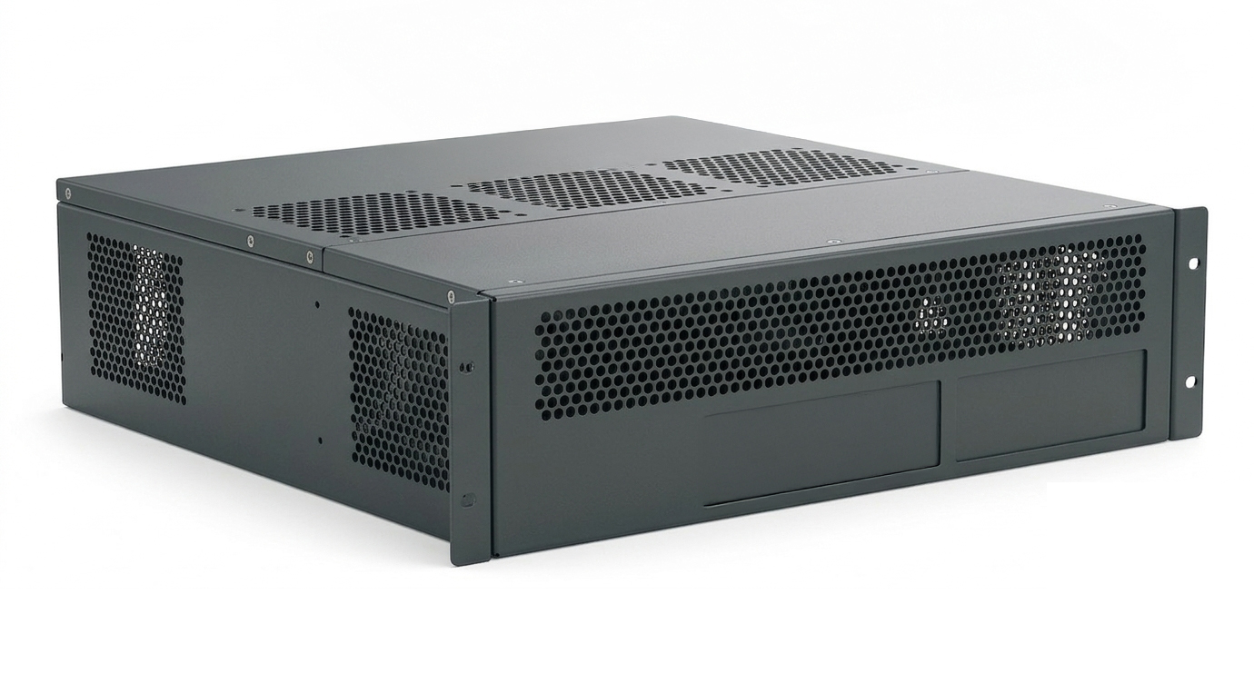
This approach is especially important for enclosure panels, equipment brackets, electronic housings, medical device frames, telecom cabinets, and precision mounting plates. A part that passes inspection after punching can still fail after coating or bending if the final process condition is not reflected in the drawing.
Tolerance Stack-Up in Sheet Metal Fabrication
A typical sheet metal part goes through blanking, bending, surface treatment, and assembly. Each process adds its own variation. The variation does not disappear between processes. It moves forward and accumulates. Hole position deviation from NCT punching can affect bend references. Bend angle variation can affect enclosure width. Coating thickness can reduce hole clearance. Press-fit hardware can shift local flatness.
For example, a 1.0 mm SPCC part may have a punched hole position tolerance of ±0.10 mm. Bending may add ±0.15 mm to ±0.25 mm of flange variation. Powder coating may add 0.06 mm to 0.12 mm of film thickness per side. When these factors are combined, the final assembly condition can differ from the original design intent by more than 0.30 mm.
This is why tolerance planning should separate functional dimensions from non-functional dimensions. Mounting holes, alignment holes, press-fit holes, mating surfaces, gasket surfaces, and electrical contact areas need tighter control. Decorative holes, ventilation slots, and non-critical outer profiles can usually follow general tolerances. The tolerance budget should be concentrated on dimensions that affect function and assembly.
NCT Turret Punching Accuracy
NCT turret punching forms holes and profiles by shearing the sheet between a punch and a die. Dimensional accuracy is affected by punch-to-die clearance, material strength, sheet thickness, tool wear, clamping condition, part nesting, and punching sequence. Even when the CAD drawing is correct, the actual punched result can vary if tool condition or material condition changes.
Punch-to-die clearance is usually set as a percentage of material thickness. For SPCC cold rolled steel, 7 percent to 9 percent of material thickness is commonly used. For SUS304 and SUS316 stainless steel, 10 percent to 15 percent is often applied because of higher strength and work hardening. For AL5052 aluminum, 6 percent to 8 percent is usually suitable for thin sheet. For high-strength steel, 12 percent to 18 percent may be required to reduce tool damage.
If clearance is too small, secondary shearing, excessive tool load, and rapid punch wear can occur. If clearance is too large, burr height increases, fracture angle becomes unstable, and effective hole size may shift. A stable sheared edge should show a controlled balance of rollover, burnished zone, fracture zone, and burr.
Tool Wear and Production Variation
NCT tools wear during production. As the punch edge becomes rounded, the effective clearance increases and the cutting condition changes. This causes higher burrs, less consistent hole size, rougher fracture zones, and greater variation between early and late production lots.
Many production issues appear only after a certain number of hits. The first lot may pass inspection, while later parts fail because the punch edge has worn or the die condition has changed. For this reason, tool maintenance should be part of the tolerance plan, not only a production department concern.
Precision holes should not rely on NCT punching alone when tight fit is required. Bearing holes, dowel pin holes, guide holes, and accurate locating holes should be punched as pilot holes and finished by reaming, boring, tapping, or another secondary process. NCT punching is efficient, but it is not the best single process for high-precision cylindrical tolerance.
Surface Treatment and Dimensional Change
Surface treatment changes the final dimensions of sheet metal parts. Painting, powder coating, plating, anodizing, electropolishing, and passivation all affect the finished condition in different ways. The effect is most critical around holes, slots, threaded areas, press-fit areas, grounding surfaces, and gasket contact surfaces.
Additive surface treatments build a layer on top of the base material. Zinc plating, nickel plating, chrome plating, wet painting, and powder coating belong to this group. Outer dimensions increase by the coating or plating thickness. Inner dimensions decrease because the film builds up from both sides of the hole wall.
Anodizing behaves differently. It converts the aluminum surface into an oxide layer. Part of the oxide layer grows outward and part of it penetrates into the base material. For many anodizing conditions, approximately 40 percent to 50 percent of the oxide thickness grows outward. This means the full anodizing thickness should not be treated as simple external build-up.
Plating Allowance for Holes and Edges
Electroplating does not always form an even thickness across the entire part. Edges, corners, and protruding areas can receive more plating because of current density concentration. Recessed areas, small holes, and deep slots may receive less. This uneven distribution can make plated hole size smaller than expected.
Zinc plating is often relatively thin, while nickel plating and hard chrome plating can create more significant dimensional change. When plated dimensions matter, the drawing should identify the plating type, target thickness, inspection condition, and masking areas.
For functional holes, the punched size can be enlarged before plating, or the hole can be finished after plating. For general bolt clearance holes, adding 0.10 mm to 0.20 mm of extra clearance is often practical. For precision fits, masking or post-plating reaming is usually more reliable. Critical dimensions should clearly state whether they apply before or after surface treatment.
Powder Coating Clearance
Powder coating provides strong corrosion resistance and durable appearance, but it also creates a relatively thick film. A cured film thickness of 0.06 mm to 0.12 mm per side is common, and thicker coatings may be specified depending on the product requirement.
This film thickness can reduce hole size and create assembly interference. A clearance hole that looks acceptable before coating may become too tight after coating. For an M4 bolt, a nominal clearance hole may need additional allowance when powder coating is applied. If the design does not allow for coating build-up, bolts may not pass through the holes during assembly.
Corners and edges also need attention. Sharp edges often reduce coating adhesion and increase the risk of corrosion or peeling. Powder-coated parts should use edge rounding where possible, especially on exposed edges, user-contact surfaces, and outdoor parts. A small radius such as R0.5 can improve coating coverage and long-term durability.
Anodizing Growth Direction
Anodizing is widely used for aluminum parts because it improves corrosion resistance, wear resistance, and appearance. However, it must be treated carefully in tolerance design. The oxide layer does not simply sit on the surface like paint. It grows partly outward and partly inward.
For precision aluminum parts, the anodizing type and target thickness should be stated on the drawing. Type II anodizing is commonly used for appearance and corrosion resistance. Type III hard anodizing is thicker and more functional, so dimensional allowance becomes more important.
Precision holes, sliding surfaces, bearing contact areas, grounding surfaces, and press-fit locations should be reviewed before anodizing is specified. If electrical grounding is required, the anodized layer may need to be removed or masked. If press-fit hardware is installed after anodizing, the hole size must reflect the oxide growth.
Masking Requirements on Drawings
Not every feature needs the same surface treatment allowance. Applying tight coating compensation to every hole and slot increases cost and complicates inspection. A better approach is to separate functional and non-functional features.
Masking should be used where coating, plating, or anodizing must not remain. Typical masking areas include precision holes, threaded areas, grounding pads, bearing seats, electrical contact surfaces, and sealing surfaces. Silicone caps, heat-resistant tape, rubber plugs, and dedicated masking fixtures may be used depending on the treatment process.
The drawing should clearly identify masked areas. Notes such as “PLATING EXCLUDE ZONE,” “ANODIZING MASK AREA,” “PAINT FREE AREA,” or “MASK THREADS BEFORE COATING” are useful when supported by clear drawing marks. If masking is not shown on the drawing, the supplier may treat the area as a normal cosmetic surface.
Threaded and Fastening Areas
Threaded and fastening areas are highly sensitive to surface treatment. Tapped holes, clearance holes, countersinks, counterbores, and self-clinching fastener holes each require separate review.
For tapped holes, coating or plating inside the thread can increase assembly torque or prevent proper engagement. If the thread must remain clean, the drawing should specify masking, thread plugging, post-coating tap chasing, or a similar process. Notes such as “THREADS TO BE FREE OF PAINT” or “CHASE TAP AFTER COATING” help avoid ambiguity.
For clearance holes, powder coating can reduce the effective diameter. It is common to provide 0.20 mm to 0.30 mm or more of additional clearance for coated holes, depending on the bolt size and coating thickness. When assembly reliability is important, clearance should be verified after the full coating process, not only after punching.
Bending and Three-Dimensional Dimensional Change
Bending changes a flat sheet into a three-dimensional part. After bending, the important dimensions are no longer only flat hole distances and profile dimensions. Flange height, inside width, outside width, perpendicularity, parallelism, hole position in 3D space, and mating surface orientation become critical.
During bending, the outside of the bend is stretched and the inside is compressed. The neutral axis shifts toward the inside surface during plastic deformation. The K-Factor represents the location of this neutral axis relative to material thickness.
K-Factor depends on material, thickness, bend radius, V-die width, punch radius, and bending method. SPCC is often calculated with a K-Factor of 0.38 to 0.42. Stainless steel often uses 0.42 to 0.46. AL5052 is commonly closer to 0.33 to 0.38. CAD default values should not be trusted blindly for production parts.
Bend Allowance and Bend Deduction
Flat pattern accuracy depends on Bend Allowance or Bend Deduction. Bend Allowance calculates the arc length through the bend zone. Bend Deduction subtracts a calculated value from the sum of flange dimensions. Both methods can work, but the values must match the actual shop condition.
For a 90-degree bend, Bend Allowance is affected by inside radius, material thickness, and K-Factor. However, the calculated value can differ from the actual result because of V-die width, punch radius, material lot, lubrication condition, bending direction, back gauge reference, and machine setup.
For precision parts, test coupons should be bent and measured before production. The measured result should be used to adjust CAD flat pattern settings. Verified shop data is more reliable than a default CAD K-Factor.
Hole and Slot Distance from Bend Lines
Holes and slots close to bend lines can distort during bending. A round hole may become oval. A slot may stretch or pull into the bend area. Cracks can occur near slot ends when the feature is too close to the plastic deformation zone.
A common design rule is to keep the edge of a hole at least 2T plus R away from the inside bend line. T is material thickness, and R is the inside bend radius. For a 1.5 mm sheet with a 1.0 mm inside bend radius, the hole edge should be at least 4.0 mm away from the bend line.
Stainless steel and high-strength steel should often use a more conservative distance such as 3T plus R. Slots and large openings require even more attention, especially when the long axis crosses the bend line.
Relief Notch Design
Relief notches reduce stress concentration around bend ends and corner areas. They also help prevent flange interference, corner overlap, tearing, and coating defects caused by trapped liquid or sharp internal pockets.
A common starting point is to make the notch width at least 1.5 times the material thickness. The depth should extend at least one material thickness beyond the bend line. Circular relief features often use a diameter of 1.5 times to 2 times the material thickness.
Box-shaped enclosures, covers, brackets, and equipment housings often require corner relief. If relief features are omitted, the corners may overlap, open unevenly, or prevent a clean 90-degree bend. For sealed or welded enclosures, the notch shape should be designed together with welding, sealing, or gasket requirements.
Springback Compensation
Springback occurs when the elastic portion of deformation recovers after bending force is removed. Materials with higher yield strength generally show greater springback. SPCC may show 1 degree to 2 degrees of springback in a 90-degree bend. SUS304 may show 3 degrees to 5 degrees. High-strength steel can show 5 degrees to 10 degrees or more.
Springback is corrected by over-bending. For example, SUS304 may need to be bent to 85 degrees to 87 degrees to achieve a final 90-degree angle. The exact value depends on material grade, thickness, inside radius, die width, and grain direction.
Grain direction also matters. Bending parallel to the rolling direction can increase cracking risk or change springback behavior. For parts with strict angle requirements, the drawing should indicate material grain direction and bending orientation.
Multiple Bend Sequence
Parts with several bends require bend sequence planning. The first bend can usually use the flat blank edge or reference holes for accurate back gauge positioning. Later bends may depend on already formed flanges, which increases accumulated variation.
Functional dimensions should be placed early in the bend sequence when possible. If a flange includes mounting holes or critical mating surfaces, it should be bent using the most stable reference condition. Less critical flanges can be placed later in the sequence.
Box shapes also require tool interference review. A design may look correct in 3D CAD but still be difficult to bend if the flange sequence creates interference with the punch, die, or back gauge. Bend simulation or CAM review should be completed before release for complex enclosures.
Burr Direction Control
In NCT punching, burrs typically form on the die side. Burr direction affects bending quality, coating adhesion, user safety, and assembly accuracy. A burr on a visible surface can create an appearance issue. A burr on a functional surface can affect flatness or alignment.
For bent parts, the burr side should usually face the inside of the bend when practical. A burr on the outside tensile surface can become a crack initiation point during bending. For painted parts, burrs also reduce coating stability and can become an early corrosion point.
Drawings should define burr direction and burr height when necessary. Notes such as “Burr Side Down,” “Burr Direction Inside,” “Remove Burrs,” or “Max Burr Height 0.05 mm” are clearer than a general deburring instruction. Deburring method should also be specified for precision parts because tumbling, brushing, and roller deburring can remove different amounts of material.
SPCC Coating Offset
SPCC cold rolled steel is one of the most common materials for sheet metal fabrication. It offers stable NCT punching performance and is widely used for covers, brackets, chassis, and equipment panels.
For SPCC, punch-to-die clearance is often set at 7 percent to 9 percent of material thickness. A 90-degree bend often starts with a K-Factor of 0.38 to 0.42, then is adjusted based on actual shop results. A minimum inside bend radius of 1.0T is commonly used, but product requirements and cracking risk should still be reviewed.
SPCC parts are frequently plated or powder coated. Zinc-plated parts may need 0.05 mm to 0.10 mm of allowance around functional holes. Powder-coated parts may need 0.15 mm to 0.30 mm or more depending on coating thickness and assembly clearance. These values should be confirmed with actual supplier data.
SPHC Scale and Thickness Variation
SPHC hot rolled steel is often used for thicker structural sheet metal parts. It may have more surface scale and thickness variation than SPCC. During NCT punching, scale can affect tool life, hole quality, and surface finish.
For SPHC, clearance is often reviewed around 9 percent to 11 percent of material thickness. A larger bend radius such as 1.5T may be more stable. Hole distance from bend lines should be more conservative than SPCC, often around 2.5T plus R.
SPHC parts are often powder coated or hot-dip galvanized. Thick coating or galvanizing can create greater dimensional change than thin plating. Functional holes may require masking or post-treatment machining.
SUS304 and SUS316 Springback
SUS304 and SUS316 stainless steel provide excellent corrosion resistance and appearance, but they require careful control during punching and bending. Their high strength and work hardening increase punching load, tool wear, and springback.
For SUS304, NCT clearance is often reviewed around 10 percent to 13 percent. For SUS316, 12 percent to 15 percent may be more suitable. Bend K-Factor often starts from 0.42 to 0.46. Springback compensation may be 3 degrees to 5 degrees for SUS304 and 4 degrees to 6 degrees for SUS316.
A minimum bend radius of 1.5T is often recommended. Hole distance from bend lines should usually be at least 3T plus R to reduce distortion and cracking. Hairline direction, protective film direction, burr direction, and visible surface orientation should also be controlled on the drawing.
AL5052 and AL6061 Anodizing Control
AL5052 and AL6061 aluminum are widely used for lightweight enclosures, electronics housings, precision covers, and brackets. AL5052 has good bendability and is common in sheet metal work. AL6061 has higher strength but may require more attention during bending.
For AL5052, NCT clearance often falls around 6 percent to 8 percent, and K-Factor often starts from 0.33 to 0.38. For AL6061, clearance around 7 percent to 10 percent and K-Factor around 0.35 to 0.40 are common starting points. These values should be adjusted after test bending and actual measurement.
Aluminum surface defects often become more visible after anodizing. Clamp marks, scratches, galling, burr marks, and cut-edge defects should be controlled before finishing. Type II anodizing may require 0.01 mm to 0.03 mm of functional allowance. Type III hard anodizing may require 0.05 mm or more depending on oxide thickness and fit requirements.
High-Strength Steel Tooling and Bend Compensation
High-strength steels such as SPFC590 and SPFC780 require more conservative planning than mild steel. They increase punching load, accelerate tool wear, and create a higher risk of punch damage.
For SPFC590, NCT clearance may be reviewed around 12 percent to 16 percent of material thickness. For SPFC780, 14 percent to 18 percent may be required. Tool material such as PM-HSS or carbide may be needed depending on thickness and hole geometry.
Springback is also larger. SPFC590 may require 5 degrees to 8 degrees of compensation. SPFC780 may require 7 degrees to 10 degrees. Minimum bend radius should be increased, often around 2.0T for SPFC590 and 2.5T for SPFC780. Hole distance from bend lines should also be increased to reduce cracking risk.
Copper and Brass Plating Allowance
C1100 copper and C2680 brass are used when electrical conductivity, thermal conductivity, or decorative appearance is required. They are easier to form than many steels, but surface protection is important because scratches, dents, oxidation, and discoloration can affect quality.
For C1100 copper, NCT clearance is often reviewed around 7 percent to 9 percent, with K-Factor around 0.36 to 0.40. For brass, clearance around 6 percent to 8 percent and K-Factor around 0.38 to 0.42 are common starting points. Actual values depend on temper and hardness.
Nickel or chrome plating can affect functional holes. A plating allowance of 0.10 mm to 0.20 mm may be required depending on thickness and inspection condition. For electrical contact parts, plating thickness, contact resistance, masking, oxidation prevention, and packaging should be controlled together.
Self-Clinching Fastener Hole Control
Self-clinching fasteners are sensitive to hole size. PEM nuts, standoffs, studs, and similar hardware require controlled hole diameters. If the hole is too small, the sheet may deform excessively. If the hole is too large, push-out force and torque resistance may fail.
The surface treatment sequence also matters. Installing hardware before coating can protect the hole condition, but threads may need masking. Installing hardware after coating can keep threads clean, but the coating may crack or peel around the pressed area.
For aluminum anodized parts, hardware is often installed after anodizing. In that case, the hole must be sized with anodizing growth in mind. If electrical grounding is required, the contact zone should be masked or finished to bare metal.
Tolerance Stack-Up Analysis
Complex sheet metal assemblies require tolerance stack-up analysis. Worst-case analysis adds all tolerances in the same direction. It is conservative and useful for safety-critical products, but it can lead to unnecessary cost if applied to every dimension.
RSS analysis uses a statistical approach and often reflects production behavior more realistically. For example, three bends with ±0.25 mm variation each create ±0.75 mm in worst-case calculation, but approximately ±0.43 mm by RSS calculation.
The key is not to make every tolerance tight. Critical assembly holes, locating surfaces, gasket areas, and press-fit features should receive the strictest control. Outer cosmetic profiles and non-functional openings can often use general tolerance. Tolerance should be assigned according to function, not visual complexity.
GD&T for Sheet Metal Drawings
Simple plus-minus tolerances are often not enough for sheet metal parts. Hole patterns are better controlled with position tolerance. Mating faces may need flatness or parallelism. Bent flanges may need perpendicularity. Datum structure should reflect how the part is assembled and inspected.
GD&T helps communicate function more clearly. A four-hole mounting pattern can be controlled by position tolerance from defined datums instead of several independent linear dimensions. This improves inspection clarity and reduces unnecessary manufacturing restrictions.
General tolerances such as ISO 2768-mK can be applied to non-critical dimensions, while critical dimensions receive specific tolerances. Edge condition and burr requirements can be managed with clear edge notes. Welded sheet metal structures may require separate general tolerance standards because welding distortion can dominate final dimensions.
Prototype Verification
Even a well-calculated tolerance plan must be checked with real parts. A prototype should go through the full process: NCT punching, bending, surface treatment, hardware insertion, assembly, and inspection. Measuring only the punched blank is not enough.
Important verification items include bend angle, flange height, inside width, hole position, hole diameter, burr direction, coating thickness, plating thickness, anodizing growth, press-fit hardware torque, assembly interference, surface appearance, and grounding resistance.
Prototype data should become the baseline for production. Bend programs, tool numbers, die width, punch radius, material grade, coating condition, masking method, inspection points, and fixture conditions should be documented. Verified process conditions should be fixed before mass production begins.
Production Control
Mass production variation can come from tool wear, machine calibration, material lot changes, coating line conditions, and operator setup. A strong drawing is important, but production control is required to keep dimensions stable.
NCT tools should have inspection and regrinding intervals based on hit count, burr height, and hole size trend. Press brakes should be checked for angle accuracy and back gauge condition. Coating and plating suppliers should measure film thickness at defined locations.
For important parts, statistical process control can help identify drift before defects occur. Useful control points include press-fit hole diameter, bend-to-bend width, coated clearance hole size, hole position, and functional surface flatness.
Drawing Notes and Process Intent
A good sheet metal drawing does more than describe shape. It communicates material, thickness, surface treatment, bend direction, burr direction, datum structure, masking areas, hardware sequence, post-treatment inspection condition, general tolerance, and critical dimensions.
The drawing should clarify whether a dimension is before or after surface treatment. Fastener holes and press-fit holes should show coating allowance or masking requirements. Holes near bend lines should follow minimum distance rules or include relief features. Visible surfaces should identify burr direction and finish direction. Grounding areas should be clearly shown as paint-free or anodize-free zones.
Not every detail must be repeated on every drawing. Common rules can be managed through company design standards, while part-specific exceptions should be stated clearly on the individual drawing.
Internal Design Standards
Many sheet metal problems repeat across projects. Bolts do not pass through coated holes. Press-fit hardware becomes loose after finishing. Holes distort near bend lines. Stainless steel springs back more than expected. Paint peels near sharp burrs. Grounding surfaces fail because coating remains.
These problems should not depend on individual designer experience. A company standard should define material-specific NCT clearance, K-Factor, minimum bend radius, hole-to-bend distance, coating allowance, fastener hole clearance, masking rules, press-fit hole control, and burr height limits.
The standard should be updated with real production data. New machines, new materials, tool changes, supplier changes, and major defect cases should all feed back into the standard. This creates a common technical language between design, punching, bending, coating, quality, and assembly teams.
NCT Sheet Metal Design Control
NCT turret punching design is not only about making a hole at the correct coordinate. It is about controlling the full manufacturing route. Coating thickness, plating build-up, anodizing growth, bend deformation, springback, burr direction, hardware insertion, and final assembly all need to be considered before the drawing is released.
Surface treatment changes dimensions. Bending changes flat geometry into three-dimensional geometry. If these effects are ignored, a part can pass inspection after punching and still fail after final assembly. If the final functional condition is used as the starting point, the NCT dimensions, bend conditions, and finishing allowances can be defined more accurately.
The core of NCT sheet metal tolerance design is simple: define the final functional dimension first, quantify each process variable, and lock verified process data into the production standard. This approach reduces coated-hole interference, anodizing fit issues, bend-related hole distortion, press-fit problems, and lot-to-lot dimensional variation.
추가 정보
NCT 터렛펀칭 후처리 절곡 공차 설계 기준은 판금 부품의 가공 치수, 절곡 변형, 표면처리 피막, 조립 간섭을 함께 검토하기 위한 실무 기준입니다. 이 정보는 ID METAL의 정밀 금속부품, 산업재 부품, 도면 기반 금속가공 검토 과정에서 공차와 후처리 조건을 정리하는 데 참고할 수 있습니다.
특히 NCT 펀칭, CNC 정밀가공, 정밀프레스가공, 전기접점, 구조연결 부품처럼 조립성과 반복 품질이 중요한 제조 분야에서는 최종 사용 상태를 기준으로 치수를 검토하는 것이 좋습니다.
핵심 포인트 정리
- 판금 부품의 공차는 펀칭 직후 치수보다 절곡과 후처리 이후의 최종 기능 치수를 기준으로 검토하는 것이 좋습니다.
- 분체 도장, 도금, 아노다이징은 홀 직경, 외곽 치수, 나사 체결부, 압입부에 영향을 줄 수 있으므로 사전 보정이 필요합니다.
- 절곡선 근처의 홀과 슬롯은 소성 변형 영역에 포함될 수 있어 최소 이격 거리와 릴리프 노치 설계를 함께 확인해야 합니다.
- 스테인리스와 고장력강은 스프링백이 크게 나타날 수 있으므로 실제 장비 조건과 소재 로트 기준으로 보정값을 검토하는 것이 좋습니다.
- 압입 화스너, 접지면, 베어링 시트, 정밀 홀은 마스킹 또는 후가공 기준을 도면에 명확히 남기는 것이 실무 분쟁을 줄이는 데 도움이 됩니다.
- 양산 전에는 시제품을 통해 NCT, 절곡, 후처리, 조립까지 이어지는 공정 조건을 확인하고 기준 데이터를 남기는 것이 좋습니다.
- 도면에는 일반 공차뿐 아니라 버 방향, 표면처리 후 치수 기준, 마스킹 영역, 기능 치수, 검사 조건을 함께 정리하는 것이 효과적입니다.
자주 묻는 질문
NCT 터렛펀칭 후처리 절곡 공차 설계 기준을 검토할 때 어떤 항목을 먼저 확인해야 하나요?
먼저 최종 조립 상태에서 중요한 기능 치수를 확인하는 것이 좋습니다. 이후 NCT 펀칭 공차, 절곡 변형, 표면처리 피막 두께, 나사 체결부와 압입부의 실효 치수를 순서대로 검토하면 공차 누적 문제를 줄이는 데 도움이 됩니다.
분체 도장이나 도금이 있으면 홀 치수를 얼마나 키워야 하나요?
피막 두께, 홀 용도, 체결 부품 규격, 조립 간극에 따라 달라집니다. 일반 체결 홀은 여유를 늘려 검토할 수 있지만, 정밀 압입 홀이나 위치 결정 홀은 마스킹 또는 후처리 후 재가공을 함께 검토하는 것이 좋습니다.
절곡선 가까이에 홀이 있으면 어떤 문제가 생길 수 있나요?
절곡 중 소성 변형 영역에 홀이 포함되면 원형 홀이 타원형으로 변하거나 슬롯 끝단에 균열이 생길 수 있습니다. 홀 가장자리와 절곡선 사이의 거리를 확보하고, 필요한 경우 릴리프 노치나 응력 완화 컷을 적용하는 것이 좋습니다.
CNC 정밀가공부품과 정밀프레스가공 부품은 어떤 기준으로 구분하나요?
CNC 정밀가공은 도면 기반의 절삭가공, 복잡 형상, 소량 정밀 부품 검토에 적합한 경우가 많습니다. 정밀프레스가공은 박판 부품, 반복 생산, 금형 기반 양산성을 함께 검토할 때 비교 기준이 될 수 있습니다.
전기접점 부품은 판금 공차 설계와 어떤 관련이 있나요?
전기접점 부품은 접촉 안정성, 통전 경로, 표면 상태, 조립 위치가 중요합니다. 도금 두께, 접촉면의 버, 압입 위치, 절곡 후 평탄도는 전류 전달 안정성에 영향을 줄 수 있으므로 도면 단계에서 함께 검토하는 것이 좋습니다.
브레이징 및 금속접합소재를 선택할 때 중요한 점은 무엇인가요?
접합 대상 소재, 사용 온도, 접합 강도, 전기적 특성, 표면처리 조건을 함께 확인하는 것이 좋습니다. 이종금속 접합이나 전기적 기능이 필요한 부품은 접합부의 형상과 후처리 조건까지 함께 검토해야 합니다.
케이블 와이어 하네스 제작 전 어떤 정보를 준비하면 좋나요?
회로 구성, 커넥터 사양, 전선 규격, 길이, 사용 환경, 고정 방식, 조립 공간 정보를 준비하면 검토가 수월합니다. 판금 하우징이나 구조연결 부품과 함께 사용되는 경우에는 배선 경로와 간섭 여부도 함께 확인하는 것이 좋습니다.
ID METAL 관련 기술 자료는 어디에서 더 확인할 수 있나요?
정밀 금속부품, 전기접점, CNC 가공, 프레스가공, 금속접합 관련 자료는 ID METAL 인사이트와 각 제품 정보 페이지에서 함께 확인할 수 있습니다. 제품 검토 전에는 도면, 소재, 공차, 후처리, 사용 환경 정보를 정리해 두면 상담과 비교 검토에 도움이 됩니다.
관련 주제 확장
정밀 금속부품 검토 기준
정밀 금속부품을 검토할 때는 형상 구현 가능성보다 최종 기능 조건을 먼저 확인하는 것이 좋습니다. 도면상 치수, 실제 조립 기준, 표면처리 후 변화, 검사 방법이 서로 맞아야 합니다. 특히 NCT, CNC machining, press parts처럼 공정 특성이 다른 부품은 같은 공차라도 실제 관리 난도가 달라질 수 있습니다.
CNC 정밀가공과 프레스가공의 선택 관점
CNC 정밀가공은 복잡 형상, 후가공 정밀도, 소량 또는 다품종 부품 검토에 적합한 경우가 많습니다. 정밀프레스가공은 반복 생산, 박판 성형, 금형 기반 치수 반복성이 중요한 부품에서 검토할 수 있습니다. 두 공정 모두 도면 공차, 소재 특성, 후처리 조건, 검사 기준을 함께 비교해야 합니다.
전기접점과 금속접합 공정
전기접점은 접촉 저항, 도금층, 접촉 압력, 표면 오염, 조립 위치에 민감한 부품군입니다. 브레이징 및 금속접합소재는 이종금속 접합이나 전류 전달 구조에서 비교 기준이 될 수 있습니다. 접점 부품을 검토할 때는 electrical contacts, brazing materials, metal joining 조건을 단독으로 보지 않고 사용 환경과 조립 구조까지 함께 확인하는 것이 좋습니다.
도면, 소재, 공차, 표면처리 정보
산업재 부품 문의 전에는 도면 파일, 소재명, 두께, 목표 공차, 표면처리, 수량 범위, 사용 환경을 정리하는 것이 좋습니다. 확인되지 않은 조건은 제작 가능 여부나 비용 판단에 영향을 줄 수 있습니다. 특히 후처리 후 치수가 중요한 경우에는 가공 후 기준인지 최종 처리 후 기준인지 도면에 명확히 표시하는 것이 도움이 됩니다.
관련 내부 자료
관련 기술 자료와 제조업 적용 사례는 ID METAL 인사이트에서 함께 확인할 수 있습니다.
도면 기반 절삭가공과 정밀 금속가공을 비교해야 한다면 CNC 정밀가공부품 항목을 참고할 수 있습니다.
박판 금속부품, 금형 기반 양산, 판재 부품 검토가 필요하다면 정밀프레스가공 부품 정보를 함께 살펴보는 것이 좋습니다.
체결, 리벳, 조립 구조와 관련된 부품은 구조연결용 부품 페이지가 비교 기준이 될 수 있습니다.
전류 전달과 접촉 안정성이 중요한 부품을 검토한다면 전기접점 제품 정보도 함께 확인할 수 있습니다.
관련 키워드
아래 키워드는 본문 주제와 함께 검토할 수 있는 제조업 검색 확장 표현입니다.