ENGLISH EDITION · INSULATION BY DESIGN
The small walls inside a power strip
Metal carries the connection. Insulating parts help keep separate connections in their intended places. Explore the relationship through Subony product photographs and an interactive structural model.
01 · Connection and separation belong together
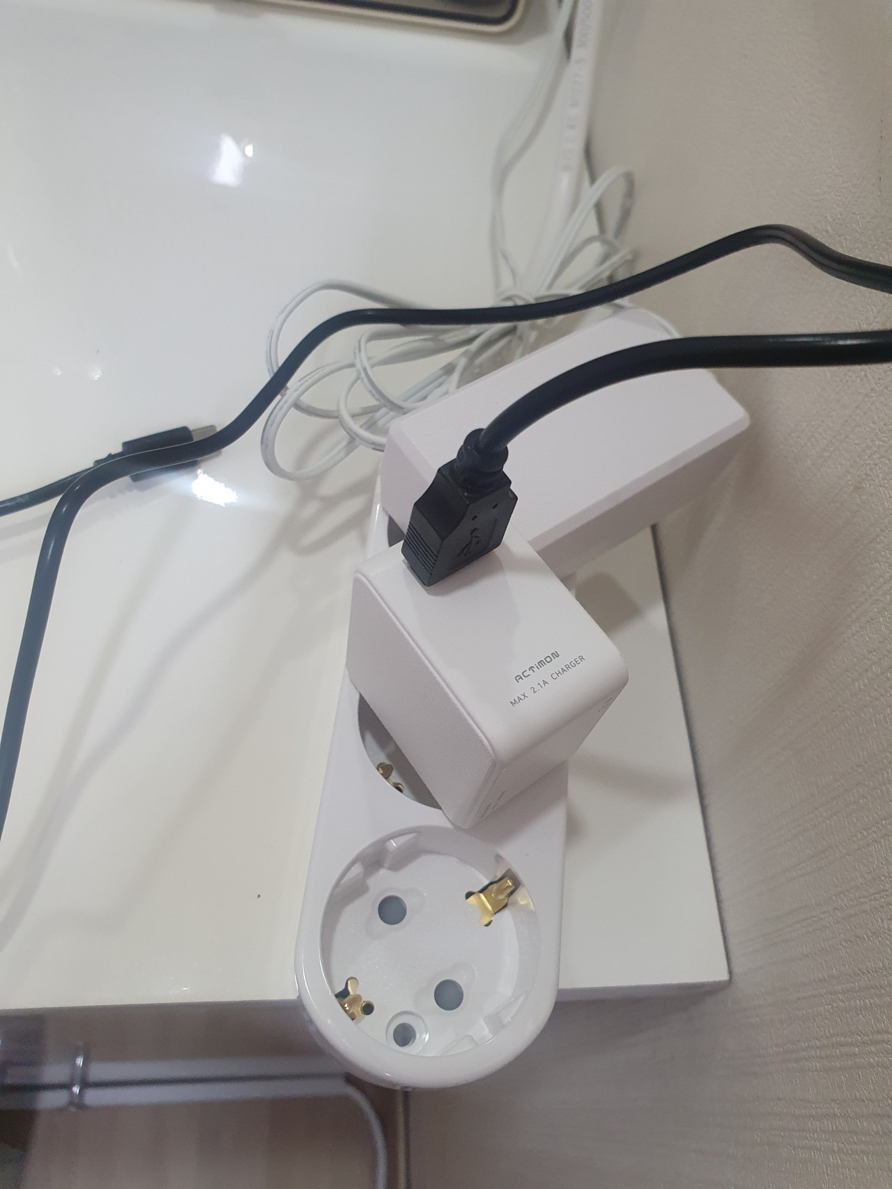
The first things we usually notice about a power strip are its outlet count and switches. Look more closely at one socket, however, and another part of the design becomes visible. Plastic surrounds the pin openings and the protective earth contacts. The metal parts occupy a shared enclosure, but they do not all have the same electrical role or connection.
In an ordinary grounded supply cable, two conductors supply the connected appliance and a third provides protective earth. The two AC supply conductors should not be described as fixed battery positive and negative terminals. Protective earth is also distinct from the normal supply circuit. Insulating components help maintain the required separation between conductive parts with different roles.
This is the starting point for understanding the housing: connect what should be connected and separate what should remain separate. The plastic does not detect leakage current or operate a circuit breaker. Its contribution is structural and insulating, working alongside the other components that make up the finished product.
02 · A barrier and a support have different jobs
An internal wall creates a boundary between metal parts. A shaped seat, groove or pillar helps locate a terminal. Sometimes one molded feature contributes to both functions. Seen this way, the enclosure is more than a container with an empty space inside; its shape helps organize the components that share that space.
The Subony internal structure photograph examined for this article shows white partitions between metal elements and molded features supporting them. This observation does not establish a universal internal layout for every model. Outlet count, switch arrangement and the particular product design can change the positions and shapes involved.
Plug insertion and removal also apply mechanical forces to the socket assembly. Terminal retention and surrounding supports work together to maintain the intended positions. That is why insulation should be understood through both material and construction. Knowing a resin name alone does not explain how the finished assembly holds its conductive parts apart during use.
03 · Explore the relationship in three dimensions
Start with the transparent housing scene. It reveals metal elements and the insulating features around them in a shared view. The second scene emphasizes partitions and supports so that their contribution is easier to distinguish from the conductors. Drag to change the viewing angle, use the zoom controls for a closer look, or pause the gentle rotation.
The third scene changes to an enlarged section between two metal parts. Select the air route and then the surface route. Both begin and end at the same conductive elements, yet their paths differ. This comparison is the main purpose of the model. It explains a relationship without presenting unverified internal measurements for a particular retail model.
The colored lines represent distance paths, not current flowing across insulation. There is no normal operating current animation through the barrier. The Korean and English controls describe the same scenes, and the reset control returns the model to its initial viewing angle.
04 · Clearance follows the shortest air path
Clearance is the shortest distance through air between conductive parts. Without an obstruction, imagine a line joining their nearest points. If an insulating wall occupies that space, an air path cannot pass through the solid wall. It must go over or around the obstacle, and the shortest available route is the relevant one.
The teal line in the model illustrates an air route over the barrier. It is deliberately different from a line drawn straight through the plastic. In a real assembly, the designer must also consider whether a shorter route exists around an end or in another direction. A single attractive view of a component cannot resolve that question.
External body width is therefore not a substitute for checking internal clearance. The required conditions depend on the applicable product requirements and electrical environment. The illustration explains how to think about the path; it does not assign a clearance rating or a measured gap to the photographed power strips.
05 · Creepage follows the insulating surface
For creepage, imagine laying a thin thread along the insulating surface between two metal parts. The shortest eligible surface route is the distance being considered. Unlike the air route, this path stays on the surface. In the enlarged model, the orange line travels along the base, climbs the barrier, crosses its top and descends on the other side.
A shaped partition can change that surface route even when the overall footprint remains similar. This helps explain why a small internal feature can matter beyond its appearance. However, a taller rib is not automatically proof of a better finished product. Other possible paths and the measurement rules for the particular geometry must also be considered.
Surface conditions matter as well. Moisture and contamination can affect electrical behavior along an insulating surface. Material properties and the intended environment therefore belong in the assessment. It would be misleading to judge the complete insulation system from rib height alone or to treat a clean-looking photograph as an electrical test.
06 · Two distances, plus the solid material itself
Clearance and creepage describe different paths between conductive parts. Meeting the need for one does not remove the need to address the other. Solid insulation introduces another consideration: the material between the parts has its own thickness, electrical properties and evaluation requirements. These ideas are related, but they are not interchangeable.
The side-by-side route view makes that distinction visible. Teal identifies the path through air; orange identifies the path along the surface. Neither line claims that electricity normally travels that way. They are visual aids for understanding separation and the features that influence its geometry.
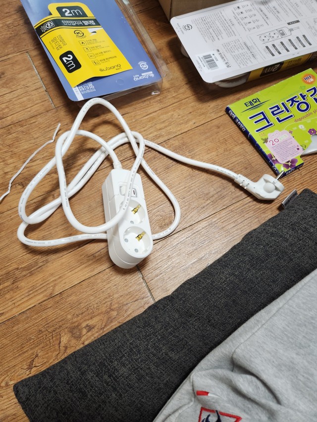
The same basic reasoning applies to different outlet counts. A two-outlet body and a six-outlet body require their own arrangements of connections, switches where fitted, supports and insulating features. Similar external styling does not prove identical internal construction. The product photographs in this article show the actual exterior, while the model explains the broader structural principle.
07 · Flame behavior is not the same as electrical insulation
A plastic component can have several important characteristics. Its behavior when exposed to a flame is one; its electrical properties are another. Its ability to retain shape under mechanical and thermal conditions also matters. These characteristics need their respective evidence rather than being inferred from a single familiar label.
For example, a UL 94 V-0 classification concerns burning behavior under specified test conditions. It does not, by itself, tell a reader the internal clearance, creepage distance or dielectric performance of a complete power strip. Likewise, a broad material family such as PC or ABS does not fully identify the particular resin grade and construction.
When reading a material description, ask what the statement actually establishes. Does it describe flame behavior, an electrical property, or a mechanical characteristic? Keeping those questions separate makes the product information more useful. It also avoids turning one genuine material feature into an unsupported promise about every aspect of the finished assembly.
08 · Read the finished product without opening it
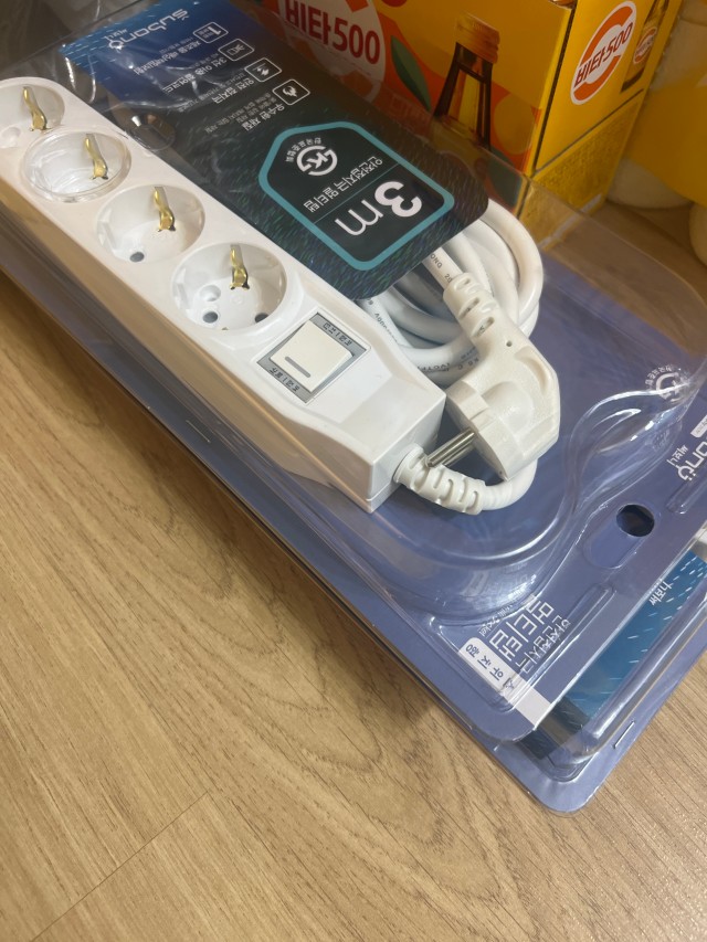
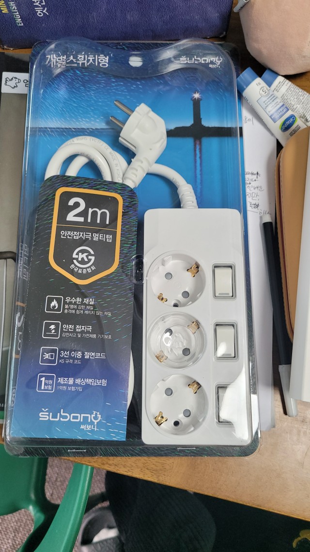
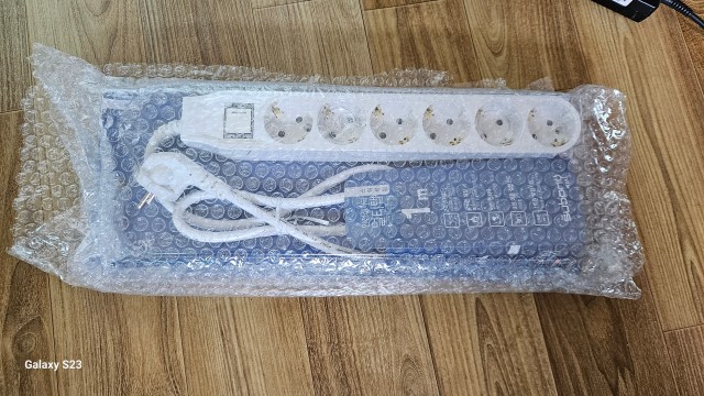
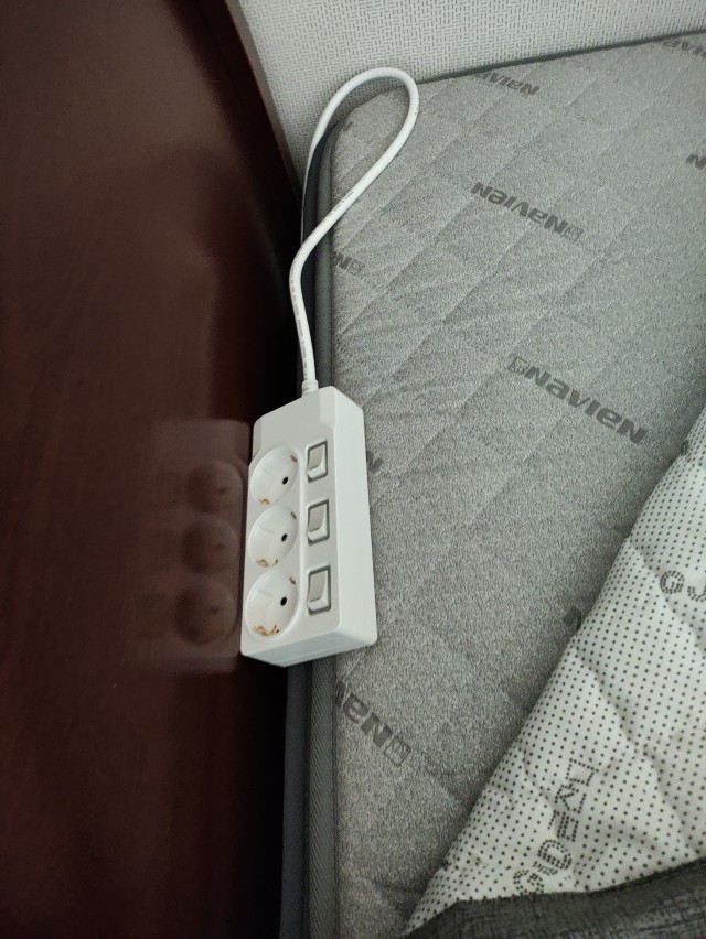
The next time you look at a Subony power strip, notice the housing around the sockets as well as the buttons. The shape surrounding the conductive parts belongs to the product design too. The outer surface and the internal arrangement form a working assembly, rather than two unrelated features.
Users do not need to dismantle the housing to measure its internal gaps. A practical check starts with the model identification, ratings, certification markings and use instructions. From the outside, look for changes such as cracks around a socket, deformation or serious discoloration. A damaged housing is not restored to its intended construction simply by covering a gap with tape.
Adding an improvised internal divider is not an appropriate substitute for the designed insulating structure either. The useful takeaway is straightforward: metal provides the intended connections, while insulating shapes help preserve the intended separation. Understanding both gives a more complete picture of the power strip than counting outlets alone.