전기 접점 신뢰성 평가를 위한
검사 장비 운용 전략과 품질 연계 구조
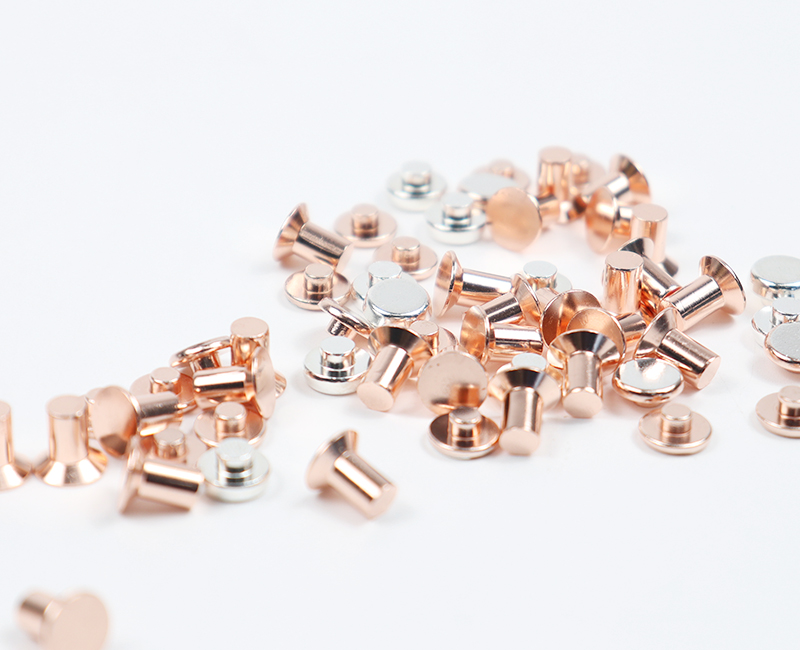
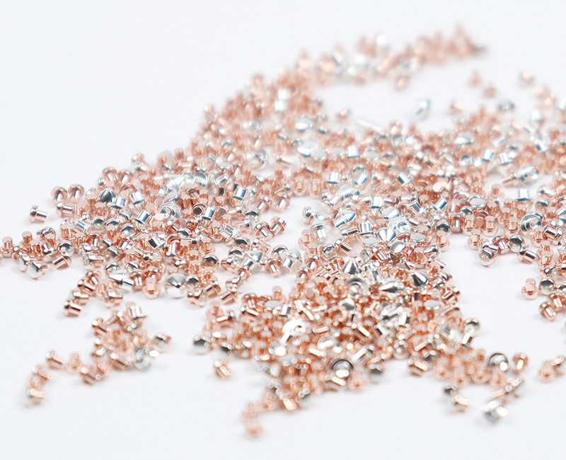
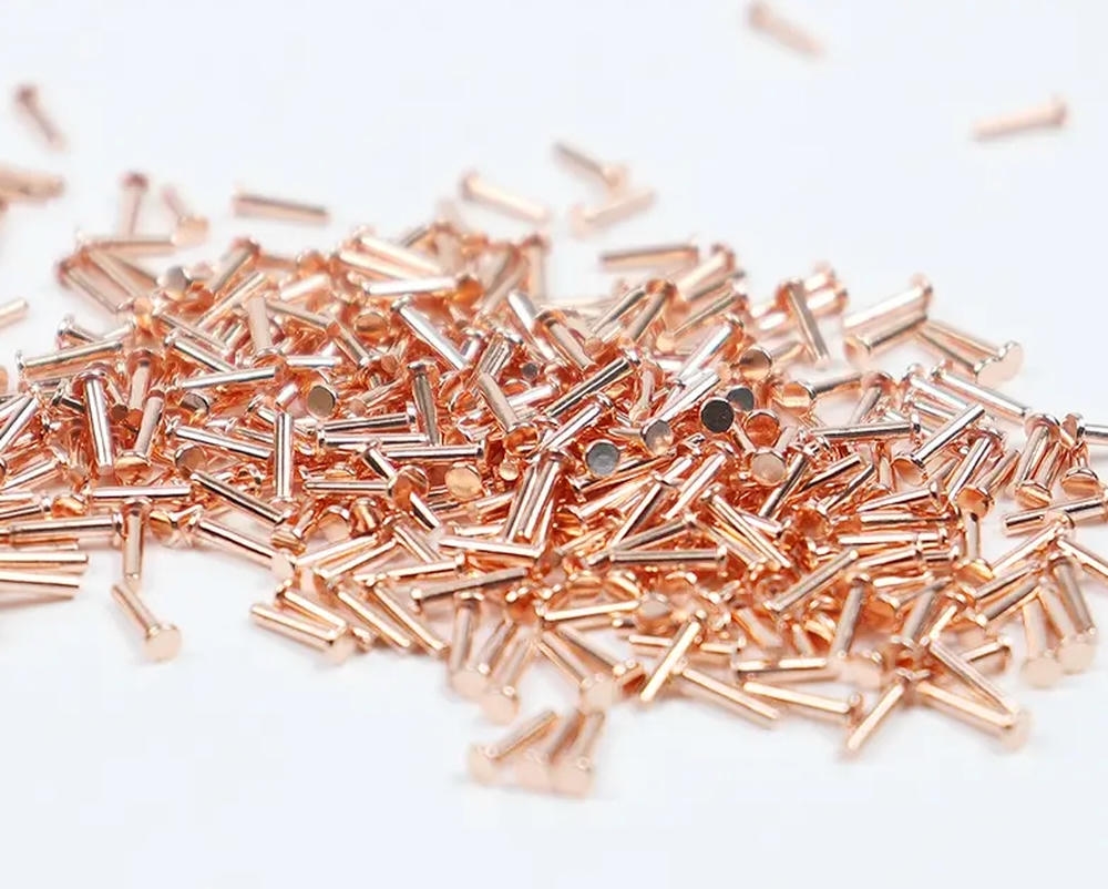
전기 접점은 단순히 전류를 전달하는 금속 부품이 아니라, 재료·형상·표면·공정 조건이 동시에 작동하는 기능성 부품입니다. 외형상 문제가 없어 보이는 접점이라 하더라도, 실제 사용 환경에서는 접촉 저항 상승, 미세 마모, 산화, 박리와 같은 형태로 성능 저하가 누적될 수 있습니다. 이러한 특성 때문에 전기 접점의 신뢰성 평가는 단일 시험이나 특정 장비의 결과로 판단할 수 없으며, 검사 장비 자체보다도 검사 체계의 설계가 핵심이 됩니다.
검사는 합격 여부를 판단하는 절차가 아니라, 공정이 정상 상태를 유지하고 있는지를 확인하는 수단으로 정의되어야 합니다. 즉, 어떤 품질 특성을 관리 대상으로 설정하고, 해당 특성을 어떤 물리적 원리로 검증하며, 그 결과가 공정 조건에 어떻게 환류되는지가 검사 체계의 완성도를 결정합니다.
전기 접점 신뢰성을 구성하는 핵심 품질 요소
전기 접점의 신뢰성은 전기적 특성, 기계적·재료적 특성, 형상·치수 특성이 동시에 안정될 때 확보됩니다. 이들 요소는 서로 독립적이지 않으며, 어느 하나의 미세한 변화가 시간이 지남에 따라 다른 특성의 열화로 연결되는 구조를 가집니다.
전기적 관점에서는 기준 온도에서의 접촉 저항 안정성이 기본 조건이 됩니다. 일반적으로 20 °C 기준에서 측정되는 저항값이 반복 접촉 이후에도 일정 범위 내에서 유지되는지가 중요하며, 이때 저항 상승의 원인이 마모, 산화, 도금층 미세 박리인지 구분할 수 있어야 합니다. 또한 도금층이나 기지재의 조성 변화로 인해 저항 편차가 확대되지 않는지도 함께 관리되어야 합니다.
기계적·재료적 특성에서는 표면 및 근표면 경도, 도금층의 두께와 구조, 내부 결함의 존재 여부가 핵심입니다. 프레스, 절삭, 연마, 디버링 과정에서 발생하는 가공경화나 열영향은 접촉 안정성을 저해할 수 있으며, 도금층 내부의 기공이나 계면 박리는 장기 신뢰성 저하로 직결됩니다. 이러한 요소는 외관 검사만으로는 확인하기 어렵기 때문에, 목적에 맞는 시험 방법이 필요합니다.
형상과 치수는 실제 접촉 면적과 접촉 압력 분포를 결정하는 요소입니다. 접촉부의 평면도, 원통도, 모서리 형상, 미세 변형은 상대 부품과의 정렬 상태와 마찰 거동에 영향을 주며, 이는 다시 접촉 저항과 마모 특성으로 이어집니다.
검사 단계별 역할과 운용 방향
전기 접점의 검사 체계는 출하 검사, 공정 감시, 심층 분석의 세 단계로 구분하여 설계하는 것이 합리적입니다.
출하 검사는 빠르고 재현성이 높은 비파괴 항목을 중심으로 구성됩니다. 치수, 도금 두께, 성분, 기준 온도 저항과 같은 항목을 통해 로트 단위의 합격 여부를 판단하며, 검사 결과는 명확한 기준값과 비교되어야 합니다.
공정 감시는 이상 발생 이후가 아니라, 변동이 발생하는 초기 단계에서 이를 감지하는 데 목적이 있습니다. 도금 두께, 저항, 핵심 치수와 같은 항목을 짧은 주기로 샘플링하여 추세를 확인하고, 기준에서 벗어나는 방향성이 나타날 경우 즉시 공정 조건을 점검합니다.
심층 분석은 이상 로트나 고객 클레임 발생 시 수행되며, 단면 분석, 경도 측정, 미세 형상 분석 등을 통해 원인을 구조적으로 규명합니다. 이 단계의 결과는 출하 기준과 공정 관리 기준을 재정의하는 근거 자료로 활용됩니다.
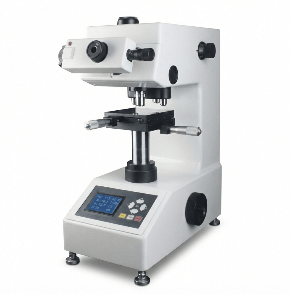
HV 경도 측정을 통한 표면 상태 관리
HV 경도 측정은 전기 접점에서 단순한 강도 평가를 넘어, 표면 상태와 공정 영향을 확인하는 지표로 활용됩니다. 접촉부 근표면의 경도가 과도하게 상승한 경우, 미세 균열이나 파편 발생 가능성이 커지며, 이는 반복 접촉 과정에서 저항 상승으로 이어질 수 있습니다.
도금층의 경우에도 경도는 중요한 의미를 가집니다. 은이나 주석 계열 도금은 공정 조건에 따라 결정립 구조와 내부 응력이 달라지며, 이로 인해 경도와 연성이 함께 변화합니다. 경도가 지나치게 높아지면 균열과 박리에 민감해지고, 반대로 너무 낮을 경우 마모에 의한 두께 감소가 빨라질 수 있습니다.
얇은 도금층에서는 기지재의 영향이 커지므로, 측정 하중과 압흔 크기, 측정 위치를 표준화하지 않으면 데이터의 신뢰성이 떨어집니다. 따라서 경도 값 자체보다도 로트 간 분산, 위치별 편차, 공정 변경 전후의 변화 추이를 관리하는 것이 중요합니다.
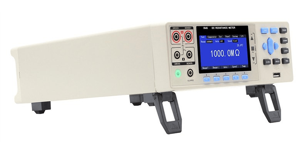
기준 온도 저항 측정과 데이터 해석
전기 접점의 저항은 마이크로옴에서 밀리옴 수준까지 측정되는 경우가 많으며, 이 영역에서는 측정 시스템 자체가 결과에 큰 영향을 미칠 수 있습니다. 4선식 켈빈 측정 방식은 리드선과 클램프의 접촉 저항 영향을 최소화하기 위한 기본 조건입니다.
측정 시점의 온도 역시 중요한 변수입니다. 현장 온도가 기준 온도에서 벗어날 경우, 재료의 온도 계수에 따라 저항이 변하므로, 내부 기준에 따라 온도 보정을 적용해야 로트 간 비교가 가능합니다.
클램핑 압력, 접촉 위치, 측정 전 안정화 시간과 같은 요소를 고정하지 않으면, 측정 결과는 공정 품질이 아니라 측정 조건의 산포를 반영하게 됩니다. 저항 데이터는 도금 두께, 조성, 형상 데이터와 함께 해석될 때 원인 추적성이 확보됩니다.
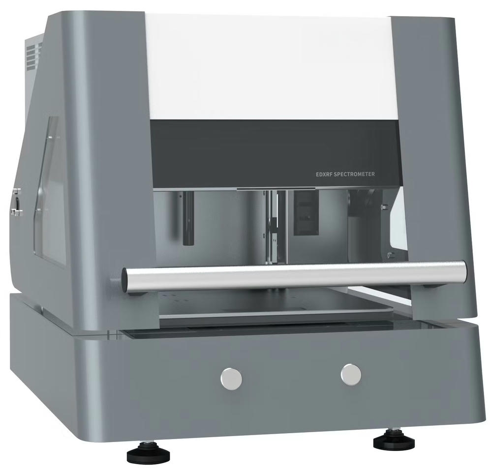

ED-XRF를 활용한 도금 두께와 조성 관리
ED-XRF는 전기 접점 검사에서 비용 대비 효과가 높은 비파괴 분석 수단입니다. 다층 도금 구조를 사용하는 경우, 각 층의 두께 균일성은 접촉 저항과 내식성에 직접적인 영향을 미칩니다.
XRF 두께 측정은 스폿 크기, 표면 곡률, 기지재 조성, 다층 모델 설정에 따라 결과가 달라질 수 있으므로, 제품별로 표준 시편이나 단면 분석을 통해 교정 체계를 유지해야 합니다.
성분 분석 측면에서는 은 계열 접점에서 미량 원소 변화가 경도와 산화 거동에 영향을 줄 수 있으며, 기지재에서의 확산이나 오염은 장기적인 저항 상승으로 이어질 수 있습니다. RoHS 스크리닝 역시 공급망 관리 관점에서 중요한 역할을 하며, 현장에서는 로트 차단을 위한 확인 수단으로 활용됩니다.
XRF는 단순한 측정 장비가 아니라, 조성과 두께 변동을 감시하는 공정 센서로 운용될 때 그 가치가 극대화됩니다.
3차원 형상 측정을 통한 접촉 안정성 확보
전기 접점의 치수 관리는 단순한 길이와 폭의 문제가 아니라, 접촉 압력 분포와 정렬 상태를 포함하는 3차원 형상 관리로 확장되어야 합니다. 접촉식 3차원 측정기는 형상과 치수의 추적성 확보에 유리하며, 비접촉식 방식은 연성 소재나 미세 부품에서 변형 없이 빠른 측정이 가능합니다.
분해능 수치만으로 장비 성능을 판단하기보다는, 온도 관리, 측정 프로그램의 표준화, 게이지 반복성 검증을 포함한 운영 체계가 중요합니다. 이러한 체계가 갖춰질 경우, 치수 데이터는 합격 여부 판단을 넘어 금형 마모나 가공 조건 변화를 조기에 감지하는 지표로 기능합니다.
비전 측정과 투영기의 현장 활용
비전 기반 측정은 빠른 처리 속도와 반복성이 요구되는 전기 접점 생산 환경에서 실용적인 장점을 가집니다. 모서리 형상, 슬롯, 펀칭 윤곽과 같은 2차원 특징치를 반복적으로 확인할 수 있으며, 작업자의 접근성도 높습니다.
다만 조명 조건, 반사 특성, 에지 검출 설정에 따라 결과가 달라질 수 있으므로, 제품별 조건을 문서화하고 주기적으로 동일 조건 재측정을 통해 데이터 안정성을 확인해야 합니다.
투영기는 형상 이상을 즉각적으로 발견하는 데 유리한 장비로, 신규 금형 적용이나 셋업 변경 이후 초기 품질 확인 단계에서 효과적입니다. 정밀 수치보다는 형상 이상을 빠르게 걸러내는 방어 수단으로 배치하는 것이 적합합니다.
전기 접점 신뢰성 판단의 관점
전기 접점의 신뢰성은 특정 검사 시점의 결과가 아니라, 여러 품질 특성이 동시에 안정적으로 유지되는 상태가 반복되는지를 통해 판단됩니다. 접촉 저항, 표면 상태, 형상 정밀도, 재료 특성은 상호 연관되어 있으며, 한 요소의 변화는 일정 시간이 지난 후 성능 저하로 나타나는 경우가 많습니다.
따라서 신뢰성 관리는 개별 수치를 확인하는 방식이 아니라, 품질 지표들의 흐름과 상관관계를 관리하는 구조로 접근해야 합니다. 이상이 발생한 뒤 원인을 찾는 것이 아니라, 변화의 징후를 조기에 감지하고 공정 조건을 조정할 수 있는 상태가 곧 신뢰성이 됩니다.
전기 접점의 신뢰성은 별도로 강조해야 할 특성이 아니라, 정상적인 공정 운영이 지속될 때 자연스럽게 확인되는 결과입니다. 이러한 관점에서 검사 장비는 품질을 증명하는 수단이 아니라, 품질을 유지하기 위한 도구로 자리 잡아야 합니다.
Inspection Equipment for Evaluating Electrical Contact Reliability
Operational Strategy for Inspection Equipment and a Quality-Linkage Structure
Electrical contacts are not merely metal parts that carry current. They are functional components where material, geometry, surface condition, and process parameters operate together. Even when a contact looks acceptable right after production, performance degradation can accumulate in real service conditions through rising contact resistance, micro-wear, oxidation, and plating delamination. For this reason, reliability evaluation for electrical contacts cannot be determined by a single test or a single instrument. The core is not the equipment list itself, but how the inspection system is designed and operated.
Inspection should be defined as a method to verify whether the process remains in a stable, controlled state, rather than a procedure that simply decides pass or fail. In other words, the completeness of an inspection system depends on which critical quality characteristics are selected, which physical principles are used to validate them, and how the results are fed back into process control.
Core Quality Elements That Define Electrical Contact Reliability
Electrical contact reliability is established only when electrical characteristics, mechanical and material characteristics, and geometric and dimensional characteristics are stable at the same time. These factors are not independent. A small shift in one area often becomes the trigger for deterioration in another area as time passes.
From an electrical perspective, stability of contact resistance at a reference temperature is the baseline requirement. In many cases, the key is whether resistance measured at 20 °C remains within a controlled range after repeated mating cycles. At that point, it is essential to differentiate whether the resistance increase comes from wear, oxidation, or micro-delamination of the plating layer. In addition, resistance variation should not widen due to changes in plating composition or base material composition.
From a mechanical and material perspective, the key items include surface and near-surface hardness, plating thickness and layer structure, and the presence or absence of internal defects. Work hardening and thermal influence generated during pressing, cutting, polishing, and deburring can reduce contact stability. Porosity inside the plating layer or interfacial delamination is directly connected to long-term reliability loss. These risks are rarely visible through appearance checks alone, so inspection methods must match the failure mechanisms being controlled.
Geometry and dimensional quality determine real contact area and contact pressure distribution. Flatness, cylindricity, edge conditions, and micro-deformation affect alignment with mating parts and the friction behavior during cycling, which then feeds into resistance stability and wear progression.
Role and Direction by Inspection Stage
A practical inspection system for electrical contacts is best designed in three stages: release inspection, process monitoring, and deep failure analysis.
Release inspection is built around fast and repeatable non-destructive items. Dimensions, plating thickness, composition screening, and reference-temperature resistance are commonly used to determine lot acceptance. The outputs must be evaluated against clearly defined specifications and decision rules.
Process monitoring is not for after-the-fact detection. It exists to detect drift early, before it becomes a reliability issue. Key items such as plating thickness, resistance, and critical dimensions are sampled at short intervals to track trends. When directional deviation appears, process parameters must be reviewed immediately.
Deep analysis is performed for abnormal lots or customer claims. Cross-section evaluation, hardness measurements, and micro-geometry correlation are used to identify root causes in a structured way. Findings from this stage should feed back into the release criteria and the process-control criteria, strengthening the overall system.
Surface Condition Control Through HV Hardness Measurement
HV hardness measurement in electrical contacts is more than a basic strength check. It is used as an indicator that reveals surface condition and process influence. If near-surface hardness in the contact region rises excessively, the probability of micro-cracking or particle generation increases, and this can lead to resistance growth during repeated contact.
Hardness is also meaningful for plated layers. Silver- or tin-based plating can develop different grain structures and internal stress depending on process conditions, which changes hardness and ductility together. If hardness becomes too high, sensitivity to cracking and delamination increases. If hardness becomes too low, thickness loss from wear can accelerate.
When plating is thin, the substrate strongly affects the measured value. If test load, indent size, and measurement location are not standardized, data reliability falls quickly. For electrical contacts, the most important control focus is not the absolute hardness number, but lot-to-lot dispersion, location-based variation, and the shift trend before and after process changes.
Reference-Temperature Resistance Measurement and Data Interpretation
Electrical contact resistance often must be measured in the micro-ohm to milli-ohm range. In this range, the measurement system itself can dominate the result if it is not controlled. A 4-wire Kelvin configuration is a baseline requirement to minimize the influence of lead and clamp resistance.
Measurement temperature is also a major variable. If the shop-floor temperature deviates from the reference condition, resistance will shift based on the material’s temperature coefficient. To enable meaningful lot comparisons, a consistent internal rule for temperature recording and reference-temperature correction should be established and applied.
If clamping force, contact location, and stabilization time before reading are not fixed, the outcome reflects measurement variation rather than process quality. Resistance data becomes far more actionable when interpreted together with plating thickness, composition screening, and dimensional data, because it improves traceability for separating thickness loss, composition shift, and geometric contact-area change.
Plating Thickness and Composition Control Using ED-XRF
ED-XRF is one of the most cost-effective non-destructive analysis methods for electrical contact inspection. For multi-layer plating structures, thickness uniformity by layer directly affects contact resistance stability and corrosion behavior.
XRF thickness results depend on spot size, surface curvature, base material composition, and multi-layer model settings. For that reason, each product should maintain an internal calibration and verification structure using reference coupons and periodic confirmation through cross-section correlation.
From a composition perspective, small changes in minor elements can influence hardness and oxidation behavior in silver-based contacts. Diffusion or contamination from the substrate can shift surface-layer composition over time and often correlates with long-term resistance increase. RoHS screening is also important for supply-chain control, and XRF is effective as a lot-screening tool for blocking risk at incoming or in-process stages.
The most effective use of XRF is not treating it as a stand-alone tester, but operating it as a monitoring sensor for detecting thickness and composition drift, with traceability built into standards, conditions, operators, and lot history.
Contact Stability Through 3D Geometry Measurement
Dimensional control for electrical contacts should extend beyond basic length and width measurement into 3D geometry management that captures pressure distribution and alignment. Contact-type CMM systems provide strong traceability and standardization for geometry and dimensional outputs. Non-contact optical or laser systems enable fast measurement without deformation for small or ductile parts.
Rather than relying on resolution claims alone, stable operation depends on temperature control, standardized measurement programs, and validation of measurement repeatability. When this structure is established, dimensional data becomes more than a pass/fail result. It becomes an early-warning indicator for mold wear, tool wear, and subtle process drift.
Practical Use of Vision Measurement and Profile Projectors
Vision-based measurement provides practical advantages in electrical contact production where throughput and repeatability are critical. It supports repeated checks of 2D features such as edges, slots, punched outlines, and small radii, with high accessibility for shop-floor operators.
However, vision results are sensitive to illumination settings, surface reflectivity, and edge-detection parameters. Product-specific setups must be documented, and periodic re-measurement under the same conditions should be used to confirm data stability.
Profile projectors are effective for immediate detection of shape abnormalities, especially during first-article approval after new tooling or setup changes. In many cases, their strength is not numerical precision but fast visual screening that catches burrs, tearing, chipping, or deformation before they spread into larger quality issues.
How Electrical Contact Reliability Should Be Judged
Electrical contact reliability is not defined by a single inspection point in time. It is defined by whether multiple quality characteristics remain stable together and whether that stability repeats consistently over time. Contact resistance, surface condition, geometry precision, and material characteristics interact. A small shift in one area may not show immediate failure, but it often becomes the starting point for later performance loss.
For this reason, reliability control should focus on managing the flow and correlation of quality indicators rather than checking isolated numbers. The goal is not to identify the cause after a problem occurs, but to detect early signals of drift and adjust process conditions before reliability is compromised.
In this framework, inspection equipment is not primarily a tool for proving quality at shipment. It is a control instrument for keeping quality stable during normal production, so that reliability becomes a natural outcome of a well-managed process.
추가 정보
전기 접점 신뢰성 평가는 단일 합격 판정이 아니라, 접촉저항·도금 두께/조성·표면 상태·미세 형상이 동시에 안정되는지를 확인하는 관리 구조입니다. 검사 장비는 측정값을 남기는 도구가 아니라, 공정 변동을 조기에 감지하고 원인 추적성을 확보하는 체계의 일부로 운용되는 것이 중요합니다.
핵심 포인트
- 기준 온도(예: 20 °C)에서의 접촉저항 안정성과 반복 접촉 후 저항 상승 패턴을 함께 확인하는 것이 필요합니다.
- 4선식(켈빈) 측정과 지그 고정, 안정화 시간 통일이 측정 산포를 줄이는 기본 조건입니다.
- ED-XRF는 도금 두께와 조성 변동을 비파괴로 감시하는 데 유리하며, 제품별 교정과 주기 검증이 전제되어야 합니다.
- HV 경도는 가공경화·열영향·도금층 특성 변화를 드러내는 지표로 활용되며, 절대값보다 분산과 위치 편차가 관리 포인트입니다.
- CMM/비접촉 3D 측정은 접촉면적과 접촉압 분포에 영향을 주는 형상 요소를 관리하는 데 적합합니다.
- 비전 측정과 투영기는 조명·반사·에지 검출 조건을 표준화해야 반복성이 확보됩니다.
- 단면 분석은 이상 로트 또는 클레임 시 XRF 교정 검증과 계면 결함(기공·박리·크랙) 규명에 직접 연결됩니다.
- 결과 데이터는 개별 항목보다 상관관계(두께·조성·형상·경도·저항)를 함께 보며 공정 피드백으로 환류되어야 합니다.
FAQ
전기 접점 저항 측정은 왜 4선식(켈빈) 구성이 필요한가요?
전기 접점의 저항은 µΩ~mΩ 영역까지 내려가는 경우가 많아 리드선과 클램프 접촉저항의 영향이 상대적으로 커집니다. 4선식은 전류 인가선과 전압 검출선을 분리하여 측정 시스템 기여도를 줄이고, 로트 간 비교의 일관성을 높이는 데 유리합니다.
저항 데이터가 흔들릴 때 공정 문제와 측정 문제를 어떻게 구분하나요?
먼저 지그 압력, 접촉 위치, 산화막 처리(프리-스크럽), 안정화 시간을 표준화한 후 동일 시편을 반복 측정해 산포를 확인합니다. 그 다음 ED-XRF 두께/조성과 치수 데이터를 함께 비교하면, 도금 부족·조성 변화·실접촉면적 변화 중 어느 쪽이 원인인지 분리하기가 쉬워집니다.
ED-XRF로 도금 두께를 볼 때 결과가 달라지는 주요 원인은 무엇인가요?
스폿 크기 대비 형상 영향, 표면 곡률과 거칠기, 기지재 조성, 다층 모델 설정이 결과에 영향을 줍니다. 제품별 측정 위치를 고정하고, 표준 시편 또는 단면 확인으로 교정·검증 체계를 유지하는 것이 운영 안정성에 도움이 됩니다.
HV 경도는 접점 신뢰성과 어떤 관계가 있나요?
접촉부 근표면의 가공경화나 열영향이 커지면 미세 균열·파편 발생 가능성이 높아져 반복 접촉 후 저항 상승으로 연결될 수 있습니다. 도금층 경도 변화는 결정립과 내부응력 변화의 신호가 될 수 있으므로, 로트 간 분산과 위치별 편차를 함께 관리하는 것이 중요합니다.
3차원 측정(CMM/비접촉)은 어떤 품질 특성을 확인하는 데 효과적인가요?
평면도·원통도·직각도·모서리 R·버·미세 변형과 같은 형상 요소는 접촉압 분포와 정렬 오차에 영향을 줍니다. 3D 측정은 합격 판정뿐 아니라 금형/공구 마모, 성형 조건 드리프트를 조기에 감지하는 공정감시 지표로 활용될 수 있습니다.
비전 측정이 도금된 부품에서 어려운 이유는 무엇인가요?
도금 광택과 반사 특성 때문에 조명 조건, 초점, 임계값, 에지 검출 알고리즘에 따라 결과가 달라질 수 있습니다. 제품별로 조명(링/동축/백라이트)과 기준선 정의를 문서화하고, 주기적으로 동일 조건 재측정을 수행하는 것이 반복성을 높입니다.
투영기는 어떤 상황에서 특히 유용한가요?
윤곽 비교, 버·찢김·치핑·변형과 같은 형상 이상을 빠르게 발견하는 데 효율적입니다. 신규 금형, 셋업 변경 후 초기품(First Article) 확인 단계에서 방어벽 역할로 배치하면 현장 대응 속도를 높일 수 있습니다.
단면 분석은 언제 해야 하고, 무엇을 확인하나요?
이상 로트 또는 클레임 발생 시, 마운팅-절단-연마 후 계면의 기공, 박리, 크랙, 오염층과 같은 결함을 확인합니다. 단면 결과는 XRF 두께 모델의 검증 및 도금 전처리·응력·오염 원인 규명에 연결되어 공정 재설계 근거가 됩니다.
출하 검사와 공정 감시에서 같은 항목을 측정해도 목적이 다른가요?
출하 검사는 로트 합격 판단을 위해 빠르고 재현성 있는 비파괴 중심으로 구성됩니다. 공정 감시는 변동을 조기에 감지하는 목적이므로, 같은 항목이라도 샘플링 주기와 관리 기준이 더 민감하게 설계되는 경우가 많습니다.
관련 주제 확장
측정 시스템 검증과 게이지 R&R의 의미
전기 접점과 같이 미세한 차이가 성능으로 연결되는 제품에서는 측정 시스템의 반복성과 재현성이 품질 판단의 기반이 됩니다. 게이지 R&R은 공정 변동인지 측정 산포인지 분리하는 기준을 제공하며, 측정자·지그·환경 조건을 표준화하는 출발점이 됩니다. 특히 저항, 비전, 3D 측정은 운용 조건에 따라 산포가 커질 수 있으므로, 내부 규격으로 절차를 고정하는 것이 유리합니다.
온도 관리가 치수와 저항에 미치는 영향
금속은 열팽창을 가지므로 장비실과 워크 온도 편차가 치수 결과에 영향을 줄 수 있습니다. 저항 또한 재료의 온도 계수에 따라 변하므로, 측정 시점 온도 기록과 기준 온도 환산 규칙을 함께 운영하는 편이 안정적입니다. 온도 관리와 열평형 시간은 고정밀 측정에서 운영 품질을 좌우하는 요소로 취급되는 경우가 많습니다.
데이터 상관관계로 원인 추적성을 높이는 방식
접촉저항 상승이 관찰될 때, 도금 두께 저하인지, 조성 변화인지, 접촉부 형상 변화인지 분리하는 것이 대응 속도를 결정합니다. ED-XRF, 저항, 3D/비전 측정 데이터를 동일 로트·동일 위치 기준으로 연결하면, 원인 추적성이 크게 올라갑니다. 이 방식은 심층 분석(단면/현미경)으로 이어지는 샘플 선정에도 도움이 됩니다.
심층 분석(FA) 결과를 출하 기준에 반영하는 방법
단면에서 확인된 계면 결함이나 기공 패턴은 XRF 모델 검증과 전처리 조건 점검의 단서가 됩니다. 또한 경도 분포와 형상 변화가 반복 접촉 저항 상승과 연결되는 경우, 출하 검사 항목의 기준과 샘플링 전략을 재정의할 수 있습니다. 결과적으로 FA는 문제 해결뿐 아니라 검사 체계 자체를 강화하는 입력 데이터로 활용될 수 있습니다.
전기 접점 신뢰성 평가는 검사 항목을 나열하기보다, CTQ를 중심으로 장비 결과가 공정 조건에 어떻게 피드백되는지까지 포함해 설계될 때 운영 안정성이 높아집니다. 관련해 전기 접점 소재와 공정 관점의 배경이 필요하다면 전기 접점 소재 및 제조 방법 내용을 함께 참고하는 방식이 이해에 도움이 됩니다.