
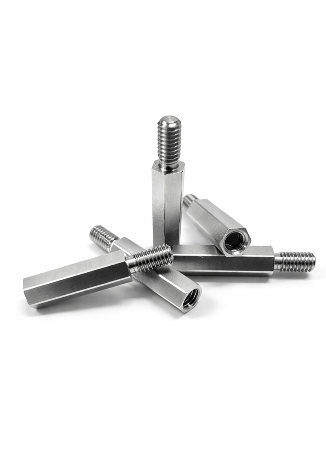
정밀 금속 가공 기술이 요구되는 육각 스탠드오프는 CNC 선삭과 엔드밀 가공의 정밀도가 체결 안정성을 좌우합니다.
CNC 가공에서의 엔드밀 적용
현대 정밀 제조 산업에서 육각 형태를 포함한 복합 형상의 부품은 항공우주, 반도체 장비, 정밀 의료기기 등 다양한 분야에서 핵심적인 역할을 수행하고 있습니다. 특히 육각 스탠드오프(Hexagonal Standoff) 부품은 단순한 체결 부품을 넘어, 부품 간의 간격을 정밀하게 유지하고 구조적 안정성을 확보하는 데 필수적인 요소입니다. 이러한 부품을 제작하기 위해서는 CNC(Computer Numerical Control) 선반 공정과 엔드밀(End-mill)을 이용한 밀링 공정이 고도로 결합된 복합 가공 기술이 요구됩니다.
고정밀 부품 제조를 위한 CNC 선삭 및 밀링 복합 가공
정밀 가공 부품의 제작은 기본적으로 원통형 소재를 회전시켜 외경을 가공하는 CNC 선삭(Turning) 공정에서 시작됩니다. 본 부품의 나사부(Threaded Part)와 단차 영역은 CNC 선반의 고속 회전과 정밀 이송 제어를 통해 수 마이크로미터(μm) 단위의 오차 범위 내에서 성형됩니다. 특히 나사산의 피치(Pitch)와 유효 지름은 체결 강도와 직결되므로, 절삭 속도와 공구 진입각에 대한 정밀 계산이 필수적입니다.
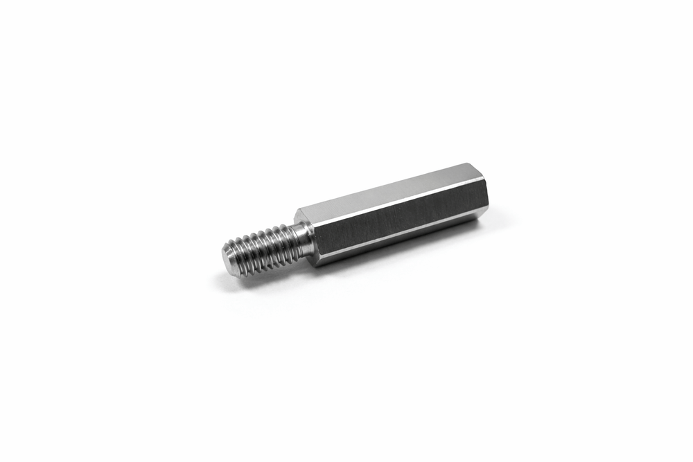
육각 형상을 갖는 몸체 부분은 엔드밀을 이용한 측면 절삭을 통해 완성됩니다. 이 공정은 흔히 ‘육각 치기’ 또는 ‘폴리곤 가공(Polygon Turning)’으로 불리며, 다축 제어가 가능한 CNC 복합 가공기에서 주축과 공구 주축의 회전을 정밀하게 동기화하여 평면을 생성합니다. 엔드밀의 날수가 증가할수록 절삭 시 발생하는 진동(Chatter)을 억제할 수 있으며, 이를 통해 표면 거칠기(Surface Roughness)를 향상시켜 거울과 같은 금속 광택을 구현할 수 있습니다.
육각 형상 가공에서의 엔드밀 절삭 메커니즘
엔드밀을 이용한 측면 절삭 공정은 고속 회전하는 절삭날이 소재의 측면을 순차적으로 제거하는 방식으로 이루어집니다. 육각 각면이 정확히 120° 기하 정밀도를 유지하기 위해서는 CNC 컨트롤러의 분할대(Indexing) 기능이 매우 정밀하게 작동해야 합니다. 이 과정에서 발생하는 절삭열은 공구 수명과 부품의 열변형에 영향을 미치므로, 고성능 절삭유(Coolant)를 사용한 냉각과 칩(Chip)의 효과적인 배출 관리가 필수적입니다.
특히 모서리부에서 발생하는 버(Burr)를 최소화하기 위해 상향 절삭(Up-cut)과 하향 절삭(Down-cut)을 경로 최적화 방식으로 조합 적용하며, 고경도 스테인리스강이나 티타늄 합금을 가공할 경우에는 코팅된 초경 엔드밀(Coated Carbide End-mill)을 사용하여 공구 마모를 최소화하고 장시간 안정적인 가공 품질을 유지합니다.
재료 선택과 가공 특성
육각 스탠드오프 가공에는 주로 스테인리스 스틸, 티타늄, 알루미늄이 사용됩니다.
스테인리스 스틸은 내식성이 뛰어나지만 가공성이 낮기 때문에 적절한 절삭 속도와 피드율 설정이 중요합니다. 예를 들어, 절삭 속도(Vc)는 140~160 SFM 범위가 일반적이며, 티타늄 합금의 경우 헬릭스 각도 45° 엔드밀을 사용하여 열 저항성과 칩 배출성을 향상시킵니다. 최근에는 태그치(Taguchi) 기법, TOPSIS 분석, 개미사자 최적화(ALO) 등과 같은 통계적·알고리즘 기반의 최적화 기법을 적용하여 표면 조도와 공구 마모를 동시에 개선하는 연구와 적용 사례가 확대되고 있습니다.
엔드밀 종류별 특징 비교
| 엔드밀 유형 | 특징 | 적용 분야 | 장점 | 단점 |
|---|---|---|---|---|
| 스퀘어 엔드밀 | 평평한 날 | 슬롯·프로파일 가공 | 범용성 우수 | 곡면 가공 부적합 |
| 볼 노즈 엔드밀 | 둥근 끝단 | 3D 곡면 가공 | 표면 품질 우수 | 칩 배출 난이도 |
| 슬롯 드릴 | 오프셋 구조 | 키웨이·슬롯 | 플런지 가공 유리 | 깊은 가공 한계 |
| 마이크로 엔드밀 | 초소형 직경 | 미세 정밀가공 | 고정밀 | 플로잉현상 가능 |
| 헬리컬 커터 | 다중 인서트 | 러핑 가공 | MRR 증가 | 고강성 장비 요구 |
표면 거칠기 및 공차 관리
표면 마감과 공차 관리
CNC 엔드밀 가공에서 표면 거칠기 기준은 일반적으로 Ra 3.2μm(125μin) 수준이며, 고정밀 가공 시 ±0.002mm 공차까지 달성 가능합니다. 업밀링과 클라임 밀링을 적절히 조합하면 칩 두께 및 열 전달을 효과적으로 제어할 수 있으며, 공구 코팅은 마모 감소 및 표면 품질 유지에 큰 역할을 합니다. 5축 CNC 장비를 사용하면 복잡 형상에서도 공차 안정성을 강화할 수 있으며, 열 변형 보정 기능을 통해 반복 정밀도를 향상시킵니다.
| 가공 매개변수 | 스테인리스 스틸 (예: 316) | 티타늄 합금 (예: Ti-6Al-4V) | 알루미늄 | 최적화 팁 |
|---|---|---|---|---|
| 절삭 속도 (SFM) | 140~160 | 160 | 500 | 열 저항 고려, 코팅 사용 |
| 피드율 (IPT) | 0.002~0.004 | 0.001~0.003 | 0.005~0.010 | 칩 로드 최적화 |
| 축방향 깊이 (ADOC) | 0.5~1.0D (D: 직경) | 0.3~0.6D | 1.0~1.5D | HEM 기법 적용 |
| 방사형 깊이 (RDOC) | 0.1~0.2D | 0.05~0.1D | 0.2~0.3D | 채터 방지 |
| MRR (in³/min) | 63.6 (예: 1/2인치 공구) | 45.2 | 80.5 | 피드 증가로 27% 향상 |
적용 분야
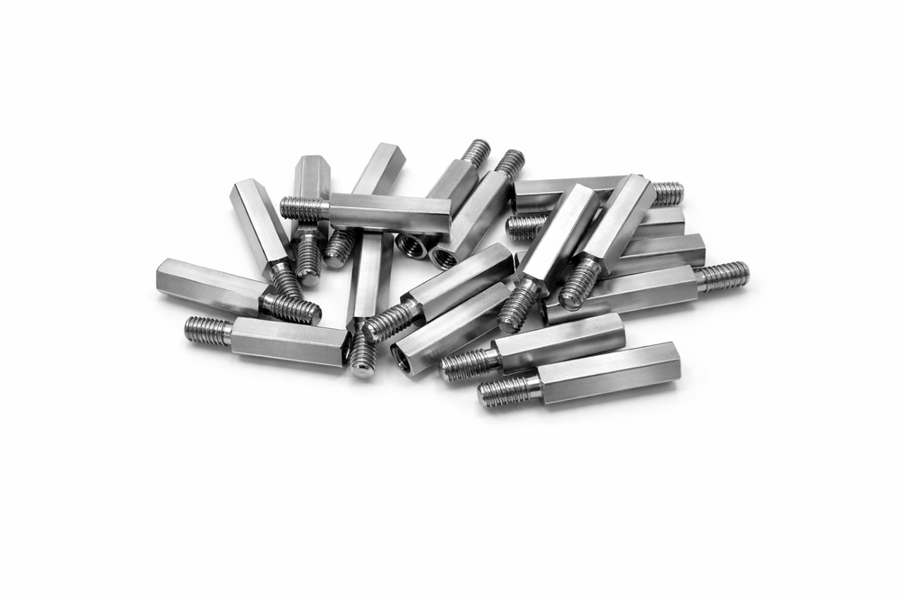
전자 산업에서 육각 스탠드오프는 PCB 고정 및 절연 간격 유지 부품으로 널리 사용되며, 대량 생산 환경에서도 CNC 복합 가공 기술을 통해 높은 정밀도와 생산성을 동시에 충족합니다. 육각부의 날카로운 모서리와 매끄러운 평면은 엔드밀의 고속 회전과 정밀 이송 제어가 완벽하게 동기화된 결과물이며, 이는 반복적인 체결 및 분해 조건에서도 마모가 최소화되는 장점을 제공합니다. 육각 스탠드오프와 같은 정밀 체결 부품은 단순한 기계 요소가 아니라, CNC 선삭과 엔드밀 밀링 기술이 융합된 고난이도 CNC 정밀가공의 결과물입니다. 공정 조건, 재료 특성, 절삭 공구, 공차 관리가 유기적으로 결합될 때 비로소 안정적이고 신뢰성 높은 품질을 확보할 수 있습니다.
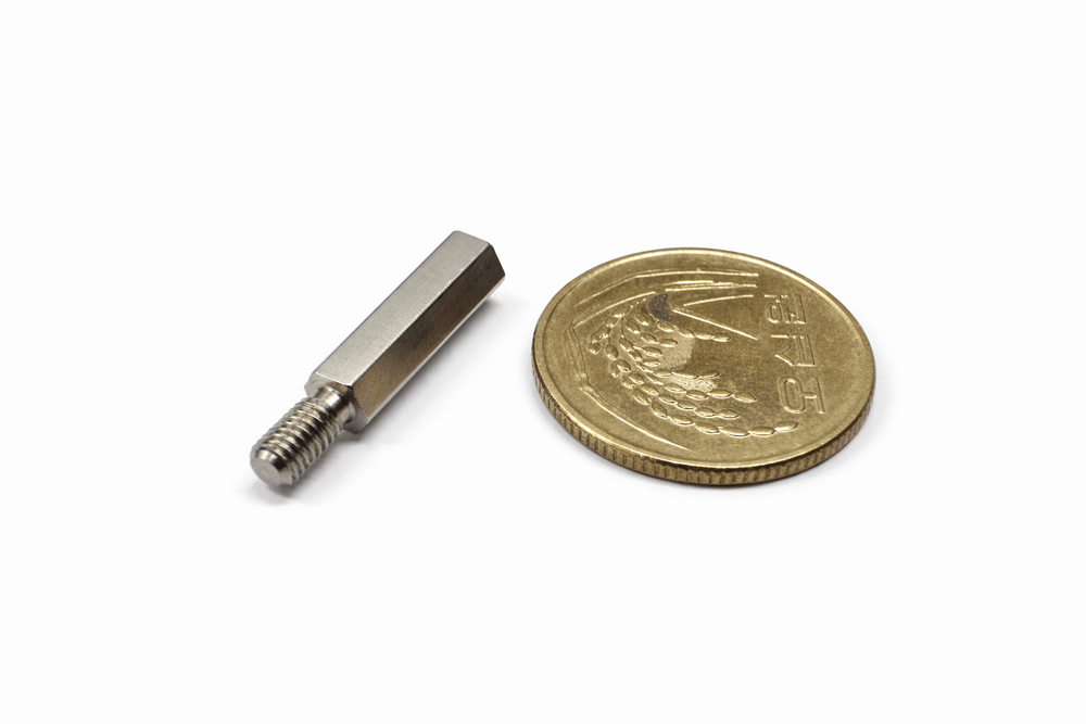
Precision Hexagonal Standoff Component — Hybrid Machining Process
Application of End-Mill Cutting in CNC Machining
In modern precision manufacturing industries, components with complex geometries—including hexagonal profiles—play a critical role across sectors such as aerospace, semiconductor equipment, and advanced medical devices. Among them, hexagonal standoff components are essential not only for mechanical fastening but also for precisely maintaining spacing between parts and ensuring structural stability.
To manufacture these components, a hybrid machining approach combining CNC turning and end-mill-based milling operations is required, enabling highly accurate and repeatable geometric precision.
CNC Turning and Milling Hybrid Machining for High-Precision Parts
Production of precision components typically begins with CNC turning, where a cylindrical raw material rotates while its outer diameter is machined. The threaded section and stepped geometry of the part are formed using high-speed spindle rotation and precise feed-rate control, achieving tolerances within micron-level accuracy. Thread pitch and effective diameter directly influence fastening strength, making accurate calculation of cutting speed and tool entry angle critical.
The hexagonal body portion is then machined using side-cut end-milling. This process—often referred to as hex-cutting or polygon machining—is performed on multi-axis CNC hybrid machines where both the work spindle and tool spindle rotations are synchronized. Increasing the number of cutting flutes helps suppress chatter vibration, improving surface roughness and achieving a mirror-like metallic finish.
End-Mill Cutting Mechanism in Hexagonal Geometry Machining
During side-cut milling, the rotating cutting edges remove material sequentially along the hexagonal surfaces. To maintain the exact 120-degree geometry between each face, the CNC controller’s indexing accuracy is crucial. Cutting heat must be controlled to prevent thermal deformation and tool wear, making the application of high-performance coolant and effective chip evacuation essential.
To minimize burr formation along edges, optimized tool paths combining both up-cut and down-cut strategies are applied. For high-hardness stainless steels and titanium alloys, coated carbide end mills are used to extend tool life and maintain dimensional accuracy over prolonged machining cycles.
Material Selection and Machinability Considerations
Hexagonal standoffs are commonly produced using stainless steel, titanium, or aluminum.
Stainless steel offers excellent corrosion resistance but relatively poor machinability, requiring careful optimization of cutting parameters such as cutting speed and feed rate. For example, cutting speeds of 140–160 SFM are typical for stainless steels, while titanium machining benefits from the use of 45-degree helix end mills to improve heat resistance and chip evacuation.
In recent years, Taguchi methods, TOPSIS analysis, and Ant Lion Optimization (ALO) have been widely applied to simultaneously improve surface finish and tool-wear performance, strengthening parameter optimization in industrial applications.
Comparison of End-Mill Types
| End-Mill Type | Key Characteristics | Typical Applications | Advantages | Limitations |
|---|---|---|---|---|
| Square End Mill | Flat end tip, 2–4 flutes | Slotting, profiling | Highly versatile, excellent flat-surface finish | Limited curved-surface capability |
| Ball Nose End Mill | Rounded tip | 3D contour & complex shapes | Smooth surface finishing on curves | Difficult chip evacuation |
| Slot Drill | Offset flat end | Keyway & slot machining | Suitable for plunge cutting, minimal deflection | Not ideal for deep cutting |
| Micro End Mill | Ultra-small diameter tools | Micro-structures, miniature parts | Extreme precision & nano-scale finishing | Possible ploughing effect |
| Helical Cutter | Multi-insert design | High-speed roughing | Increased MRR & extended tool life | Requires high-rigidity equipment |
Surface Finish and Tolerance Control
In CNC end-milling, surface roughness standards commonly target Ra 3.2 μm (125 μin), while ultra-precision machining may achieve tolerances of ±0.002 mm. Combining up-milling and climb milling allows better thermal and chip-thickness control. Tool coatings also help minimize wear and maintain consistent surface finish quality.
In complex geometries, 5-axis CNC machining enhances tolerance stability, while thermal-compensation systems improve repeatability under varying machining conditions.
Recommended Machining Parameters
| Machining Parameter | Stainless Steel (e.g., 316) | Titanium Alloy (e.g., Ti-6Al-4V) | Aluminum | Optimization Tip |
|---|---|---|---|---|
| Cutting Speed (SFM) | 140–160 | 160 | 500 | Consider heat resistance & coating selection |
| Feed Rate (IPT) | 0.002–0.004 | 0.001–0.003 | 0.005–0.010 | Optimize chip load |
| Axial Depth of Cut (ADOC) | 0.5–1.0D | 0.3–0.6D | 1.0–1.5D | Apply HEM strategy |
| Radial Depth of Cut (RDOC) | 0.1–0.2D | 0.05–0.1D | 0.2–0.3D | Prevent chatter |
| MRR (in³/min) | 63.6 (1/2″ tool example) | 45.2 | 80.5 | Feed increase may enhance MRR by 27% |
Industrial Applications
In the electronics sector, hexagonal standoffs are widely used for PCB mounting and insulation spacing. Even in mass-production environments, CNC hybrid machining technologies enable both high productivity and precision stability. The sharply defined hexagonal edges and smooth flat surfaces are proof of synchronized high-speed cutting and precision feed-rate control.
These components are not simply hardware elements; they represent the integration of CNC turning and precision end-milling technology. When machining parameters, material properties, tooling, and tolerance management are harmonized, stable and highly reliable product quality can be consistently achieved.
추가 정보
정밀 스탠드오프 가공은 단순한 가공명보다 넓은 제조 기준으로 봐야 합니다. 정밀 육각 스탠드오프 부품의 복합 절삭 가공 공정에서는 소재 특성, 공정 조건, 치수 안정성, 표면 품질, 조립 환경이 함께 맞아야 실제 부품 신뢰성이 확보됩니다.
ID METAL의 제조 기술 콘텐츠는 한 가지 장비나 공정만 분리해서 설명하기보다, 도면 요구사항과 소재 선택, 가공 순서, 후처리, 검사 기준이 어떻게 연결되는지를 중심으로 다룹니다. 작은 공차 차이나 표면 상태도 전기접점, 판금, CNC 부품에서는 기능 품질로 이어질 수 있습니다.
정밀 스탠드오프 가공 검토 기준
- 소재 규격과 실제 사용 환경을 함께 확인합니다.
- 치수 공차, 위치도, 평탄도, 표면 거칠기 같은 도면 요구를 공정 기준으로 연결합니다.
- 가공 후 버, 변형, 잔류응력, 표면 오염이 기능면에 남지 않도록 관리합니다.
- 후처리와 세척, 포장 조건까지 품질 흐름에 포함합니다.
- 반복 생산에서는 초품 기준과 양산 중 측정 기준을 분리해 관리합니다.
- 전기적 기능이 있는 부품은 접촉저항, 체결 압력, 표면막, 사용 온도까지 함께 봅니다.
제조 현장에서 함께 보는 요소
CNC 가공은 치수 정밀도만으로 끝나지 않습니다. 기준면을 어디로 잡는지, 클램핑 과정에서 변형이 생기지 않는지, 공구 마모가 표면에 어떤 흔적을 남기는지까지 봐야 합니다. 판금과 NCT 가공에서는 타공 배열, 절곡 순서, 도금이나 도장 후 치수 변화까지 연결해서 봅니다.
전기접점이나 전장 부품은 소재와 표면 상태가 더욱 민감합니다. 접촉저항이 안정적으로 유지되는지, 반복 개폐나 진동 조건에서 체결 상태가 흔들리지 않는지, 후처리 과정이 전기적 특성에 영향을 주지 않는지 확인해야 합니다.